


Ask our Experts
Didn't find what you are looking for? Ask our experts!
New Community Ranking System
Our Community ranking system has recently been updated. You may notice changes in user rankings and receive system messages or notifications. If you have questions about how the new ranking works, please refer to the announcement post for more details (click here).
Schneider Electric support forum about Power Meters (ION, PowerTag, PowerLogic) and Power Quality from design, implementation to troubleshooting and more.
Search in
Link copied. Please paste this link to share this article on your social media post.
Hello,
At our customer's facility there is a problem about Reactive Power Difference.
I tried to draw a schema, you can see below. Iskra and ION9000 use a common current transformer.
What is your idea about this problem? Is there any setting about measurement format of ION9000 ?
Link copied. Please paste this link to share this article on your social media post.
The "KVA tot Method" setup register does not affect nor configure the kVAR calculation method.
"KVA tot Method" only affects the "kVA tot" output of the power meter module and any calculation that depends on kVAtot (see ION Reference for more information)
It looks like there is no ION Setup wizard for disabling the "Use Fundamntal kVAR" method.
You will need to
1. select "Show Advanced ION Setup" in ION Setup's Device Properties window (see Tools tab),
2. navigate to the "Ext Bool Modules" and open ExtBool1 (UseFundkVAR).
3. SHIFT+click on the "Output Registers" tab to show the current configuration (default = true)
4. SHIFT+click on the output register "UseFundkVAR" and select "OFF"
5. SHIFT+click on the output register tab again to refresh (should now be false)
If you wish to implement some other method for computing kVAR (eg. Triangle method), you will need to create an Arithmetic module and configure it and link it as you wish.
Link copied. Please paste this link to share this article on your social media post.
I am not at all surprised since the Quadrature method for computing VARs is quite different from the power triangle method with distorted or non linear loads.
Fortunately the equations for the power triangle method are clearly laid out in the whitepaper you linked and trivial to implement with an Arithmetic module.
Note: Be sure to set the KVA_tot method to "Arithmetic Sum" when using power triangle VARs, otherwise you will have a circular dependency.
I am curious what reason you might have for requiring this method? Is it purely for data consistency (with old meters)?
Link copied. Please paste this link to share this article on your social media post.
Hello @Caglar_Abatay
I would consider asking a question like this in the hardware section rather than PME in the future. I will see if I can get someone to help move it.
As to the question, I would ask the simple one first, what device do you trust more, how do you know that the ION9000 meter is not the correct reading? What do the phasor diagrams look like between the devices?
Regards,
Charles
Link copied. Please paste this link to share this article on your social media post.
Differences in reactive power is usually due to harmonic content (often a non linear load) and different algorithms for measuring reactive power.
I'm guessing the "mW" and "mVAR" are intended to read "MW" and "MVAr" (Mega vs. milli prefix)?
If this is a milli-watt and milli-var load, this might be outside the nominal operational range of your meters (need to confirm PT and CT ratios).
Did you mean the "Iskra MC 350"? I cannot find information on a model "MC 35".
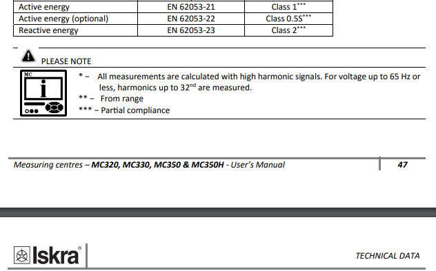
All the Iskra devices I found claim partial compliance to the legacy reactive energy spec: IEC62053-23 Class 2 (2%)
The IEC62053-23 standard only defines performance under sinusoidal steady state conditions, so that many different reactive power algorithms will comply to the mandatory tests (all tests are sinusoidal).
The ION9000 complies completely to this old standard and also to the new IEC62053-24 Class 0.5S (0.5%). The -24 standard enforces that reactive power be derived only from the fundamental component in the voltage and current signals.
My guess is that the PM870 is using the same/similar algorithm as the Iskra device.
Link copied. Please paste this link to share this article on your social media post.
Hello @Charles_Murison ,
Yes I trust ION9000 but other two devices are measuring similar value. And difference is very big. I checked phasor diagrams They look good.
Best Regards.
Link copied. Please paste this link to share this article on your social media post.
Hello @DanL
You are right the device name is Iskra MC350.
I found a document about reactive power calculation methods of Schneider analysors Last Year. "Calculation of Electrical Powers in Schneider Electric PMDs" I attached at this post.
My first idea was to change reactive power calculation methods of ION9000. That's why I wrote this topic. But I will try your advices.
The main issue that confuses me is that the value read by the PM870 is very near to the value read by Iskra.
Best Regards.
Link copied. Please paste this link to share this article on your social media post.
I believe the PM870 used the "power triangle" method for reporting VARs.
The ION9000 computes two methods of VARs by default:
1) fundamental only (the default display value and default reactive energy method) always available on the Power Harmonics module outputs
2) "Quadrature method" always available on the Power Meter module outputs
Additionally, the ION9000 can be configured to compute other methods including the "power triangle" VAR quantity with an Arithmetic module.
Link copied. Please paste this link to share this article on your social media post.
Link copied. Please paste this link to share this article on your social media post.
Hello @Caglar_Abatay
If you place the meter in advanced configuration, navigate to power meter modules -> Power meter. Under the setup registers there is KVA tot Method, Options are Vector Sum and Scalar Sum. Perhaps this will be able to do what you are looking for?
Charles
Link copied. Please paste this link to share this article on your social media post.
The "KVA tot Method" setup register does not affect nor configure the kVAR calculation method.
"KVA tot Method" only affects the "kVA tot" output of the power meter module and any calculation that depends on kVAtot (see ION Reference for more information)
It looks like there is no ION Setup wizard for disabling the "Use Fundamntal kVAR" method.
You will need to
1. select "Show Advanced ION Setup" in ION Setup's Device Properties window (see Tools tab),
2. navigate to the "Ext Bool Modules" and open ExtBool1 (UseFundkVAR).
3. SHIFT+click on the "Output Registers" tab to show the current configuration (default = true)
4. SHIFT+click on the output register "UseFundkVAR" and select "OFF"
5. SHIFT+click on the output register tab again to refresh (should now be false)
If you wish to implement some other method for computing kVAR (eg. Triangle method), you will need to create an Arithmetic module and configure it and link it as you wish.
Link copied. Please paste this link to share this article on your social media post.
Hello @DanL ,
I used Designer (PME) in order to this operation. I setted ExtBool1 (UseFundkVAR) to zero in designer. But there is a big difference at kVar values still.
I think so we need other method for computing kVAR. I will continue to research.
Thanks.
Link copied. Please paste this link to share this article on your social media post.
I am not at all surprised since the Quadrature method for computing VARs is quite different from the power triangle method with distorted or non linear loads.
Fortunately the equations for the power triangle method are clearly laid out in the whitepaper you linked and trivial to implement with an Arithmetic module.
Note: Be sure to set the KVA_tot method to "Arithmetic Sum" when using power triangle VARs, otherwise you will have a circular dependency.
I am curious what reason you might have for requiring this method? Is it purely for data consistency (with old meters)?
Link copied. Please paste this link to share this article on your social media post.
Link copied. Please paste this link to share this article on your social media post.
Link copied. Please paste this link to share this article on your social media post.
Today, we completed a series of laboratory tests with the ION7400 meter in collaboration with the Federal University of Uberlândia (UFU), Brazil. The objective of these tests is to qualify the ION7400 for a nationwide measurement campaign that will evaluate active and reactive power under harmonic conditions. Therefore, the accuracy and consistency of the meter are essential.
Our tests showed excellent consistency for active power measurements. The total active power reported by the Power Meter module matched the sum of the active power components obtained from the individual Power Harmonics modules (fundamental, 3rd, 5th, 7th, etc.), confirming that active power is internally consistent across the different modules.
However, we observed different behavior for reactive power.
Before conducting these tests, I carefully read the previous discussion "Calculation of Electrical Powers in Schneider Electric PMDs." In that document, I noticed that the reactive power calculation is described as being based on a 90° phase shift, but there is no mention of the use of a Hilbert transform or any equivalent quadrature filter. The document also acknowledges the limitations of this approach under distorted waveform conditions.
Based on our measurements and spectral analysis, we concluded that the ION7400 behaves consistently with a fixed 90° time delay (quarter-cycle delay) rather than a Hilbert transform. While both approaches produce identical results for purely sinusoidal waveforms, they behave differently when harmonic distortion is present.
As a consequence, the reactive power obtained from the Power Meter module is not equal to the sum of the reactive power components reported by the individual Power Harmonics modules. This differs from the behavior observed for active power, where both methods produce identical results.
From a signal-processing perspective, this behavior is expected. A quarter-cycle delay shifts each harmonic by an angle proportional to its harmonic order, whereas a Hilbert transform shifts every positive-frequency harmonic by exactly 90°. Therefore, under distorted conditions, the two methods lead to different reactive power values.
Could someone from Schneider Electric confirm whether this interpretation is correct? Specifically, is the reactive power algorithm intentionally based on a fixed quarter-cycle delay rather than a Hilbert transform or another digital quadrature method? Any additional technical information would be greatly appreciated, as it will help us correctly interpret the results of this nationwide measurement campaign.

You’ve reached the end of your document

Create your free account or log in to subscribe to the board - and gain access to more than 10,000+ support articles along with insights from experts and peers.