Ask our Experts
Didn't find what you are looking for? Ask our experts!
Share Your Feedback – Help Us Improve Search on Community! Please take a few minutes to participate in our Search Feedback Survey. Your insights will help us deliver the results you need faster and more accurately. Click here to take the survey
Schneider Electric support forum about installation and configuration for DCIM including EcoStruxure IT Expert, IT Advisor, Data Center Expert, and NetBotz
Search in
Link copied. Please paste this link to share this article on your social media post.
Posted: 2020-07-05 03:17 PM . Last Modified: 2024-04-03 11:28 PM
Hello experts,
I already ask a question concerning this topic, but got recently confused by a collegue. My question is, do I connect a 0/24V DigitalOutput directly on Nr 9 OR on Nr 10 with an upstream voltageconverter(0-24V to 0-5V):

In the describtion from the NetBotz is written:
9.) 4-20 mA Inputs: Provides 24 VDC for connecting third-party sensors with an input current range from 4 to 20 mA.
10.) Sensor ports: Used for connecting APC by Schneider Electric sensors, third-party dry-contact sensors, and standard third-party 0-5 V sensors. (See “Additional Options” on page 3 for details on sensor options.) Third-party dry-contact state sensors require the NetBotz Dry Contact Cable (NBES0304). Standard third-party 0-5 V sensors require the NetBotz 0-5 V Sensor Cable (NBES0305). NBRK0450/550 - 5/24 VDC (50mA). NBRK0570 - 5/24 VDC (200mA).
with best regards
Alex
(CID:137110964)
Link copied. Please paste this link to share this article on your social media post.
Link copied. Please paste this link to share this article on your social media post.
Posted: 2020-07-05 03:18 PM . Last Modified: 2024-04-03 11:28 PM
Dear Alex Rente,
Ok, this simplest task, unfortunately, is not solved only by =SE= products.
Solution 1 (best): buy NetBotz Dry Contact Cable - 15 ft. (NBES0304) for $39.99 and connect it to the universal sensor inputs (from Nr 10). Find an discrete/relay output in your 3rd party equipment, that will close/open its contacts (i.e., the output instead of your 24/0V DC voltage output). Connect it together and then your NetBotz appliance will determine the discrete state of your 3rd party equipment.
Solution 2: buy NetBotz Dry Contact Cable - 15 ft. (NBES0304) for $39.99 and connect it to the universal sensor inputs (from Nr 10). Buy a low-voltage intermediate relay with one pair of switching contacts. Connect the coil of this relay to the voltage output 24/0V DC of your 3rd party equipment. Connect the switching contacts of this relay to the cable NBES0304 and then your NetBotz appliance will determine the discrete state of your 3rd party equipment.
Both of the above solutions are the best in terms of electromagnetic protection, since your NetBotz appliance will be electrically isolated from your 3rd party equipment. It is very important in industrial conditions.
Therefore, I do not suggest you buy a NetBotz 0-5V Cable - 15 ft. (NBES0305) cable for analog solutions for $69.99. And then use a resistive voltage divider to connect it to your 3rd paty equipment, as described in your past question. Such a solution is dangerous, as the NetBotz appliance can fail due to electromagnetic surges and an overvoltage at the universal sensor input.
With respect.
(CID:137111037)
Link copied. Please paste this link to share this article on your social media post.
Link copied. Please paste this link to share this article on your social media post.
Posted: 2020-07-05 03:18 PM . Last Modified: 2024-04-03 11:28 PM
Dear Alex Rente,
There are many options and wiring diagrams. However, practically, 24V DC output (from Nr 7) can be used in conjunction with relay outputs Relay1 and Relay2.
On the other hand, the Current inputs (from Nr 9) and universal sensor inputs (from Nr 10) do not provide for the connection of power supply. On the contrary, universal sensor ports provide power for sensors, for example, for an temperature/humidity AP9335TH digital sensor.
In order to help you, we need to understand your task well.
If you have more questions, please ask.
With respect.
(CID:137111004)
Link copied. Please paste this link to share this article on your social media post.
Link copied. Please paste this link to share this article on your social media post.
Posted: 2020-07-05 03:18 PM . Last Modified: 2024-04-03 11:28 PM
Hello=)
Ok, you may misunderstood me. I got a sensor (Device 1 is working, true=24V, wrong=0V) which i want to connect to my NetBotz.
I do not need power-supply for that sensor , i just want to process the input-signal on/off.
with best regards
Alex
(CID:137111014)
Link copied. Please paste this link to share this article on your social media post.
Link copied. Please paste this link to share this article on your social media post.
Posted: 2020-07-05 03:18 PM . Last Modified: 2024-04-03 11:28 PM
Dear Alex Rente,
Ok, this simplest task, unfortunately, is not solved only by =SE= products.
Solution 1 (best): buy NetBotz Dry Contact Cable - 15 ft. (NBES0304) for $39.99 and connect it to the universal sensor inputs (from Nr 10). Find an discrete/relay output in your 3rd party equipment, that will close/open its contacts (i.e., the output instead of your 24/0V DC voltage output). Connect it together and then your NetBotz appliance will determine the discrete state of your 3rd party equipment.
Solution 2: buy NetBotz Dry Contact Cable - 15 ft. (NBES0304) for $39.99 and connect it to the universal sensor inputs (from Nr 10). Buy a low-voltage intermediate relay with one pair of switching contacts. Connect the coil of this relay to the voltage output 24/0V DC of your 3rd party equipment. Connect the switching contacts of this relay to the cable NBES0304 and then your NetBotz appliance will determine the discrete state of your 3rd party equipment.
Both of the above solutions are the best in terms of electromagnetic protection, since your NetBotz appliance will be electrically isolated from your 3rd party equipment. It is very important in industrial conditions.
Therefore, I do not suggest you buy a NetBotz 0-5V Cable - 15 ft. (NBES0305) cable for analog solutions for $69.99. And then use a resistive voltage divider to connect it to your 3rd paty equipment, as described in your past question. Such a solution is dangerous, as the NetBotz appliance can fail due to electromagnetic surges and an overvoltage at the universal sensor input.
With respect.
(CID:137111037)
Link copied. Please paste this link to share this article on your social media post.
Link copied. Please paste this link to share this article on your social media post.
Posted: 2020-07-05 03:18 PM . Last Modified: 2024-04-03 11:28 PM
Hello,
i made a little scetch..

Does that match your thoughts ?
I agree with you, that point 3 is not good. Point 2 is the same like point 1 but the relais is outside?!
And it would be very nice if you could explain me why i cant just directly connect it to Nr9. Just from logic thinking I would say it is not good, because it measures current and not voltage, fruthermore we have no defined state at 0V.
If my scetch is right, i just have another little question
with best regards
Alex
(CID:137111075)
Link copied. Please paste this link to share this article on your social media post.
Link copied. Please paste this link to share this article on your social media post.
Posted: 2020-07-05 03:18 PM . Last Modified: 2024-04-03 11:28 PM
Dear Alex Rente,
From your comments:
Does that match your thoughts ?
Absolutely correct.
I agree with you, that point 3 is not good. Point 2 is the same like point 1 but the relais is outside?!
But an intermediate relay can be placed inside your 3rd party equipment. That is, Solution 1 uses the built-in relay of your 3rd party equipment, and Solution 2 uses an additional relay. Electrically both solutions are exactly the same.
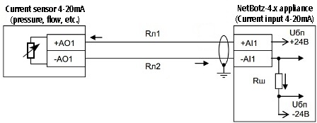
And it would be very nice if you could explain me why i cant just directly connect it to Nr9. Just from logic thinking I would say it is not good, because it measures current and not voltage, fruthermore we have no defined state at 0V.
That's right, Current inputs (from Nr 9) measure the DC current flowing through them. Accordingly, the connection scheme of current sensors is completely different. For example, like this:

With respect.
(CID:137111172)
Link copied. Please paste this link to share this article on your social media post.
Link copied. Please paste this link to share this article on your social media post.
Posted: 2020-07-05 03:18 PM . Last Modified: 2024-04-03 11:28 PM
Thank you very much. That was very helpful !!
My last question considering solution 1 and 2. I mean, I could just accept the fact that it works, but I want to know why ^^ ? When I bridge the contacts, what voltage or which level I will get then on the input and why?
Best regards
Alex
EDIT: Ahhh ich got it. I understood it 😃 Again: Thanks a lot
(CID:137111248)
Link copied. Please paste this link to share this article on your social media post.
Link copied. Please paste this link to share this article on your social media post.
Posted: 2020-07-05 03:18 PM . Last Modified: 2024-04-03 11:28 PM
Dear Alex Rente,
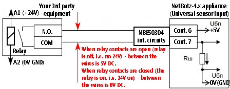
I mean, I could just accept the fact that it works, but I want to know why ^^ ? When I bridge the contacts, what voltage or which level I will get then on the input and why?
Ok, it's very simple, I think my little picture will answer your question:

More details about the connection and characteristics of the NBES0304 can be found in my answer .
With respect.
(CID:137111374)
Link copied. Please paste this link to share this article on your social media post.
Link copied. Please paste this link to share this article on your social media post.
Posted: 2020-07-05 03:18 PM . Last Modified: 2023-10-22 03:12 AM

This question is closed for comments. You're welcome to start a new topic if you have further comments on this issue.
Link copied. Please paste this link to share this article on your social media post.
You’ve reached the end of your document
Create your free account or log in to subscribe to the board - and gain access to more than 10,000+ support articles along with insights from experts and peers.