Help
  • Explore Community
  • Get Started
  • Ask the Community
  • How-To & Best Practices
  • Contact Support
Notifications
Login / Register
Community
Community
Notifications
close
  • Forums
  • Knowledge Center
  • Events & Webinars
  • Ideas
  • Blogs
Help
Help
  • Explore Community
  • Get Started
  • Ask the Community
  • How-To & Best Practices
  • Contact Support
Login / Register
Sustainability
Sustainability

Join our "Ask Me About" community webinar on May 20th at 9 AM CET and 5 PM CET to explore cybersecurity and monitoring for Data Center and edge IT. Learn about market trends, cutting-edge technologies, and best practices from industry experts.
Register and secure your Critical IT infrastructure

Investigating Modbus devices shown as offline in Sigma

Building Automation Knowledge Base

Schneider Electric Building Automation Knowledge Base is a self-service resource to answer all your questions about EcoStruxure Building suite, Andover Continuum, Satchwell, TAC…

cancel
Turn on suggestions
Auto-suggest helps you quickly narrow down your search results by suggesting possible matches as you type.
Showing results for 
Show  only  | Search instead for 
Did you mean: 
  • Home
  • Schneider Electric Community
  • Knowledge Center
  • Building Automation Knowledge Base
  • Investigating Modbus devices shown as offline in Sigma
Options
  • Bookmark
  • Subscribe
  • Email to a Friend
  • Printer Friendly Page
  • Report Inappropriate Content
Invite a Co-worker
Send a co-worker an invite to the portal.Just enter their email address and we'll connect them to register. After joining, they will belong to the same company.
You have entered an invalid email address. Please re-enter the email address.
This co-worker has already been invited to the Exchange portal. Please invite another co-worker.
Please enter email address
Send Invite Cancel
Invitation Sent
Your invitation was sent.Thanks for sharing Exchange with your co-worker.
Send New Invite Close

Related Forums

  • Intelligent Devices Forum

Previous Next
Contributors
  • Product_Support
    Product_Support
  • Cody_Failinger
    Cody_Failinger
  • sesa125819
    sesa125819

Invite a Colleague

Found this content useful? Share it with a Colleague!

Invite a Colleague Invite
Back to Building Automation Knowledge Base
Options
  • Bookmark
  • Subscribe
  • Email to a Friend
  • Printer Friendly Page
  • Report Inappropriate Content
0 Likes
1443 Views

Link copied. Please paste this link to share this article on your social media post.

Trying to translate this page to your language?
Select your language from the translate dropdown in the upper right. arrow
Translate to: English
  • (Français) French
  • (Deutsche) German
  • (Italiano) Italian
  • (Português) Portuguese
  • (Русский) Russian
  • (Español) Spanish

Investigating Modbus devices shown as offline in Sigma

Picard Product_Support
‎2018-09-09 08:37 PM

Issue

The Sigma IC3-Modbus reports that the Modbus devices are offline.

Product Line

Satchwell Sigma

Environment

  • Sigma
  • IC3 Modbus
  • IC Modbus

Cause

Communications with the Modbus devices has failed, or cannot be achieved.

Resolution

Testing of the IC3-Modbus must be carried out in a systematic way; the points listed below are only as a general guide:

  1. Confirm that the communications type, (2-wire or 4-wire) is correct for all devices connected to the Modbus 485 communications LAN. The IC3-Modbus only uses a 2-wire RS 485 LAN configuration.
  2. Ensure that the communications LAN to the Modbus devices is correctly connected.
  3. Confirm that the overall LAN length does not exceed the RS 485 maximum of 1200M.
  4. Ensure that the cable has been installed maintaining the 300mm segregation from other electrical services.
  5. Ensure that the communications cable is a Belden 8762 or similar, and that the cable screening is connected to a good earth at one end only. The other end of the screen should be isolated. (Note: In instances where high frequency noise is present, a 1uF filter can be connected between the isolated screen end and a good earth).
  6. Configure the Gateway.txt file, ensuring that the comms parameters match those of the Modbus devices. Add one object for the Modbus device nearest to the IC3-Modbus. Download the Gateway.txt to the IC3-Modbus and then warm-start it.
  7. Observe the IC3-Modbus RS 485 communications TXD/RXD LED's and confirm that the TXD is seen to flash on a regular basis. This will indicate that the Gateway.txt file is configured correctly.
  8. If the TXD and RXD LED's flash alternatively, then this suggests that normal communications is taking place.
  9. If the TXD LED does not flash, then this indicates a problem with Gateway.txt file configuration, and it will be necessary to check the "Low level Alarms" on the Sigma Default/Backup server for more information about the problem.
  10. If the TXD LED is seen to flash on a regular basis, but the RXD does not, then there are four possible conclusions:
    1. The communications cable between the two points is not continuous, or the cores are crossed.
    2. The Modbus device number does not match that set in the Gateway.txt.
    3. The register being requested is not a valid register.
    4. The Modbus device is faulty.
  11. Testing a Modbus device using a Modbus simulator.
    1. Download a Modbus simulator, there are several freeware/shareware products available on the internet.
    2. Using an RS232/RS485 converter connect directly from the PC/Laptop to the Modbus device. Review the appropriate registers to confirm if the device is working correctly.
  12. Testing that the IC3-Modbus is sending appropriate Modbus messages.
    1. Using an RS232/RS485 converter, connect from the PC/Laptop to the IC3 Modbus in parallel with the existing Modbus RS485 comms. Start PocketTerminal32.exe, select “Setup/Communication Ports” and set the comms port to match the Modbus parameters, then select “Display” and select to "Display Hex".
       
       
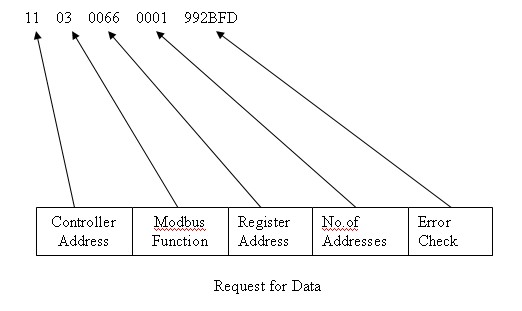
    2. The trace programme will display blocks of Hex, as shown below. The message shown below is addressed to Modbus device 11 (Decimal 17), it uses function code 3, the register address is 66 (Decimal 96), only this address is required, and the message has an error check.
      The message will be shown as 110300660001992BFD which can be split into sections.
    3. If the controller replies, the complete Request and Reply will appear as:
      110300660001992BFD110302142B3698
      Request = 110300660001992BFD
      Reply = 110302142B3698 Again this message can be split up.
      11 = controller address, 03 = Function code, 02 = Number of bytes of data, 142B = Data, and 3698 = Error check.

To download a copy of PocketTerminal32.exe please Click Here.

Labels (1)
Labels:
  • Satchwell BAS & Sigma
Attachments
PocketTerminal32.zip
Tags (1)
  • Find more articles tagged with:
  • 5204
Was this article helpful? Yes No
No ratings

Link copied. Please paste this link to share this article on your social media post.

To The Top!

Forums

  • APC UPS Data Center Backup Solutions
  • EcoStruxure IT
  • EcoStruxure Geo SCADA Expert
  • Metering & Power Quality
  • Schneider Electric Wiser

Knowledge Center

Events & webinars

Ideas

Blogs

Get Started

  • Ask the Community
  • Community Guidelines
  • Community User Guide
  • How-To & Best Practice
  • Experts Leaderboard
  • Contact Support
Brand-Logo
Subscribing is a smart move!
You can subscribe to this board after you log in or create your free account.
Forum-Icon

Create your free account or log in to subscribe to the board - and gain access to more than 10,000+ support articles along with insights from experts and peers.

Register today for FREE

Register Now

Already have an account? Login

Terms & Conditions Privacy Notice Change your Cookie Settings © 2025 Schneider Electric

This is a heading

With achievable small steps, users progress and continually feel satisfaction in task accomplishment.

Usetiful Onboarding Checklist remembers the progress of every user, allowing them to take bite-sized journeys and continue where they left.

of