
Ask our Experts
Didn't find what you are looking for? Ask our experts!
Share Your Feedback – Help Us Improve Search on Community! Please take a few minutes to participate in our Search Feedback Survey. Your insights will help us deliver the results you need faster and more accurately. Click here to take the survey
Schneider, APC support forum to share knowledge about installation and configuration for Data Center and Business Power UPSs, Accessories, Software, Services.
Search in
Free
EnglishStrengthen your foundational knowledge in Data Centers for free, enroll in this path today and start your learning journey!
Posted: 2021-06-30 07:29 AM . Last Modified: 2024-03-07 11:01 PM
Link copied. Please paste this link to share this article on your social media post.
Posted: 2021-06-30 07:29 AM . Last Modified: 2024-03-07 11:01 PM
I recently acquired 2 Smart-UPC SUA1500RM2U units. One (UPS1) appears to be functioning fine. The second (UPS2) does not charge or turn on without Cold Start mode. In my attempts to resolve the issue I have (in various combinations of orders):
Am I SOL with a dead unit? Are there other things I should try?
Link copied. Please paste this link to share this article on your social media post.
Link copied. Please paste this link to share this article on your social media post.
Posted: 2021-06-30 07:30 AM . Last Modified: 2024-03-07 11:01 PM
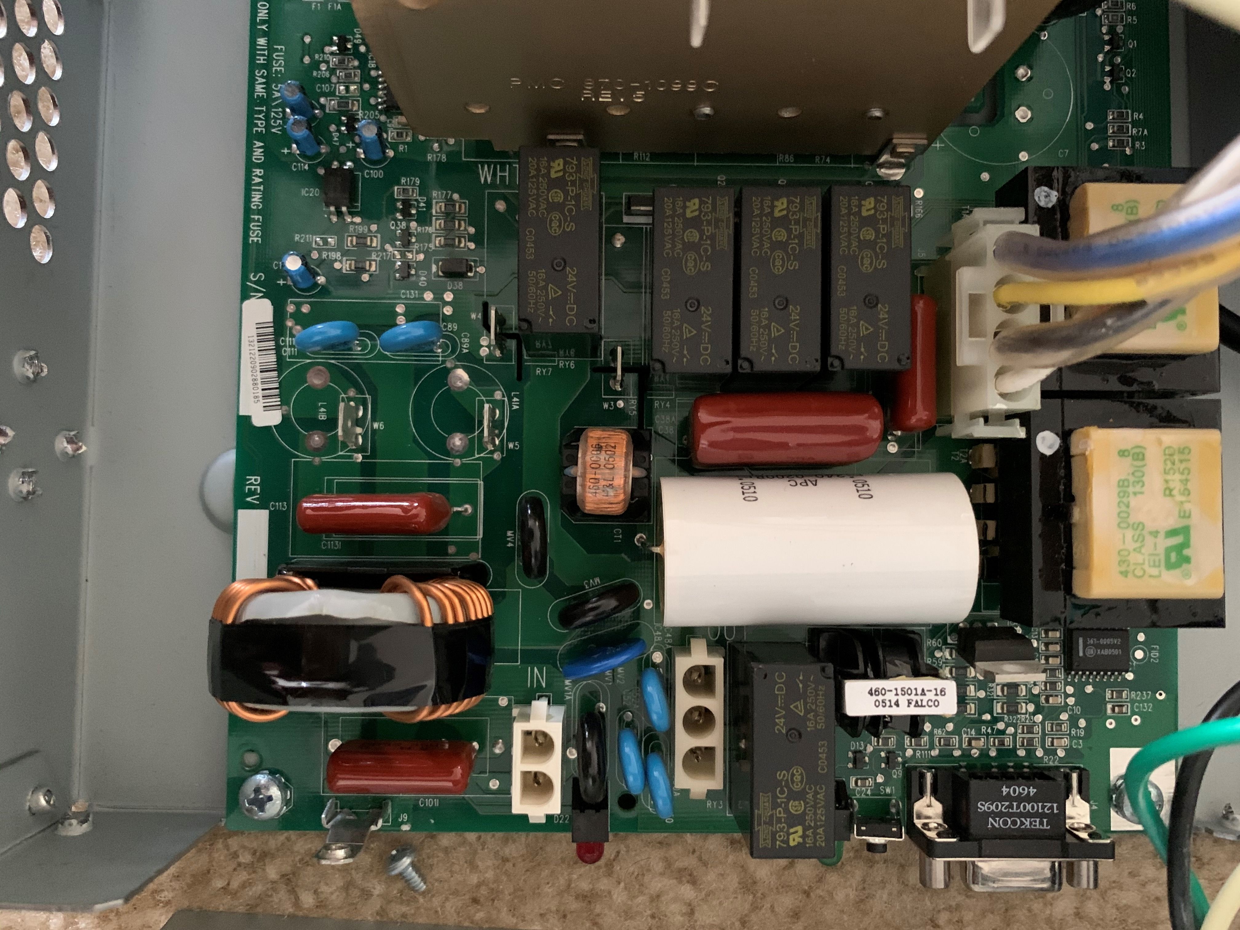
No, the transformers are on the right. White with green writing , part no "430-0029B". T1/T1A is the mains input sense and T2/T2A is the output voltage sense.
On 19/1/2020 6:12 AM, Alex said:I unplugged all of the connectors and reconnected them all. When I plugged the unit into the wall, everything worked! So I closed it up and tried it again - and it was dead.
Sounds like a dry joint, dodgy connection or mechanically faulty component. It looks like I sent you off on a wild goose chase with the fuse reference. The fuse on that board "F1" or "F1A" is in the battery circuit. There is no fuse between the mains input and the sense transformer (T1/T1A).
One thing you could do is apply gentle pressure to the board and associated components with a wooden stick. If it's a mechanical issue the flex can often show it up and help narrow it down.
It sounds like you're starting to look at a slightly more in-depth diagnosis, following PCB tracks with the meter and a few extra tests. Mains voltage can bite hard if you slip and you need to be confident with your test gear and a soldering iron.
Link copied. Please paste this link to share this article on your social media post.
Link copied. Please paste this link to share this article on your social media post.
Posted: 2021-06-30 07:29 AM . Last Modified: 2024-03-07 11:01 PM
Sounds like the unit isn't detecting the incoming mains supply. Does it have a fuse or circuit breaker on the input?
Checking an (admittedly much) older unit I have here there is a circuit breaker on the rear panel adjacent to the input socket.
Link copied. Please paste this link to share this article on your social media post.
Posted: 2021-06-30 07:29 AM . Last Modified: 2024-03-07 11:01 PM
Link copied. Please paste this link to share this article on your social media post.
Posted: 2021-06-30 07:29 AM . Last Modified: 2024-03-07 11:01 PM
Thanks for the thought!
I did check the breaker indicator on the back; it's not popped and I've tried to press it in to ensure it's engaged/disengaged (whichever direction word means "functional").
I think I may need to open the unit up to check internal breakers/fuses...
Link copied. Please paste this link to share this article on your social media post.
Link copied. Please paste this link to share this article on your social media post.
Posted: 2021-06-30 07:29 AM . Last Modified: 2024-03-07 11:01 PM
There are 2 small PCB transformers on the board. One is on the input and the other on the output. The one on the input side is used for mains presence sensing. Check you have AC at the primary and something viable (~10-15VAC RMS) on the secondary. The secondary is center tapped. Your unit sounds like a US domestic (no I in the part number), so the primary on the transformer may be two windings also.
There is usually a small PCB mount fuse in series with the primary of that transformer, so keep an eye out for that. They are generally a little axial fuse, so no glass.
I had an older unit recently where the primary of the transformer went "mostly" open circuit which caused all sorts of issues from non-detection of mains to wildly varying voltages causing the UPS to think it had welded AVR relays.
The rest of the UPS is essentially isolated from the mains by the transfer relay until the UPS decides the incoming mains is in tolerance, and it runs entirely from the battery until it senses that and pulls the relay in at which time the charger fires up.
Link copied. Please paste this link to share this article on your social media post.
Posted: 2021-06-30 07:30 AM . Last Modified: 2024-03-07 11:01 PM
Link copied. Please paste this link to share this article on your social media post.
Posted: 2021-06-30 07:30 AM . Last Modified: 2024-03-07 11:01 PM
Thanks for the details. I'm struggling to follow a lot of what you said. I can see the big coil (bottom left) and the secondary center tapped coil (center). I'm unsure how to check for voltages (where I should put the leads of the tester)...
I also do not see anything that could be a PCB mounted fuse, but it's entirely possible I have no idea what I'm looking for.
I unplugged all of the connectors and reconnected them all. When I plugged the unit into the wall, everything worked! So I closed it up and tried it again - and it was dead. I then tried to replicate this feat, and I can't get it to respond to wall power at all. However, I know it's receiving wall power, because if I take the grounding screw out, it reports a site power fault, whereas if I replace the grounding screw the power fault warning light goes out...
Link copied. Please paste this link to share this article on your social media post.
Link copied. Please paste this link to share this article on your social media post.
Posted: 2021-06-30 07:30 AM . Last Modified: 2024-03-07 11:01 PM
No, the transformers are on the right. White with green writing , part no "430-0029B". T1/T1A is the mains input sense and T2/T2A is the output voltage sense.
On 19/1/2020 6:12 AM, Alex said:I unplugged all of the connectors and reconnected them all. When I plugged the unit into the wall, everything worked! So I closed it up and tried it again - and it was dead.
Sounds like a dry joint, dodgy connection or mechanically faulty component. It looks like I sent you off on a wild goose chase with the fuse reference. The fuse on that board "F1" or "F1A" is in the battery circuit. There is no fuse between the mains input and the sense transformer (T1/T1A).
One thing you could do is apply gentle pressure to the board and associated components with a wooden stick. If it's a mechanical issue the flex can often show it up and help narrow it down.
It sounds like you're starting to look at a slightly more in-depth diagnosis, following PCB tracks with the meter and a few extra tests. Mains voltage can bite hard if you slip and you need to be confident with your test gear and a soldering iron.
Link copied. Please paste this link to share this article on your social media post.
Posted: 2021-06-30 07:30 AM . Last Modified: 2024-03-07 11:01 PM
Link copied. Please paste this link to share this article on your social media post.
Posted: 2021-06-30 07:30 AM . Last Modified: 2024-03-07 11:01 PM
I safely poked and prodded some more, and buttoned up for one final test. Seems to be working now - I have no idea what I did, but the unit is functional. Clearly I can't trust this one for a prod environment, but it will suffice for some redundancy until I can save up to replace.
Thanks for the help!
Link copied. Please paste this link to share this article on your social media post.
You’ve reached the end of your document
Create your free account or log in to subscribe to the board - and gain access to more than 10,000+ support articles along with insights from experts and peers.
