Ask Me About Webinar: Data Center Assets - Modeling, Cooling, and CFD Simulation
Join our 30-minute expert session on July 10, 2025 (9:00 AM & 5:00 PM CET), to explore Digital Twins, cooling simulations, and IT infrastructure modeling. Learn how to boost resiliency and plan power capacity effectively. Register now to secure your spot!
NetBotz 450 and sensor pod NetBotz 150
EcoStruxure IT forum
Schneider Electric support forum about installation and configuration for DCIM including EcoStruxure IT Expert, IT Advisor, Data Center Expert, and NetBotz
- Mark Topic as New
- Mark Topic as Read
- Float this Topic for Current User
- Bookmark
- Subscribe
- Mute
- Printer Friendly Page
- Mark as New
- Bookmark
- Subscribe
- Mute
- Permalink
- Email to a Friend
- Report Inappropriate Content
Link copied. Please paste this link to share this article on your social media post.
Posted: 2020-07-03 02:54 AM . Last Modified: 2024-04-09 12:08 AM
NetBotz 450 and sensor pod NetBotz 150
Hello.
After sensor change, on netbotz sensor pod 150, i try connect 450 and 150, but after connect, all icons in Netbotz advanced view go grey and all sensor reading status change to N/A.
(CID:106204277)
- Labels:
-
NetBotz
Link copied. Please paste this link to share this article on your social media post.
- Mark as New
- Bookmark
- Subscribe
- Mute
- Permalink
- Email to a Friend
- Report Inappropriate Content
Link copied. Please paste this link to share this article on your social media post.
Posted: 2020-07-03 02:54 AM . Last Modified: 2024-04-09 12:08 AM
Dear Leonid,
As far as I know, the Netbotz Sensors will be shown N/A while the Netbotz A-Link establishes the communication to the Appliance after the sensors are attached. The Sensors will show the values once the appliance senses the Pods sensors after some time. Do these sensors showing the values after some time? If so, its normal.
If the sensors are still showing N/A on the Advance View, then I request you to do the following:
Please make sure that the Sensor Pod is connected as per the A-Link Communication instructions as per user manual. If possible, Restart the appliance with the sensors and see if the values are shown on the advance view.
Please make sure that the Botzware of the appliance is the latest version.
If the problem remains same, please provide the following details:
How many sensors pods are connected to the appliance?
Is this a new installation or had it been working before?
Are there any sensors connected to the appliance? If so, are they showing the sensor values?
Botzware version.
(CID:106204300)
Link copied. Please paste this link to share this article on your social media post.
- Mark as New
- Bookmark
- Subscribe
- Mute
- Permalink
- Email to a Friend
- Report Inappropriate Content
Link copied. Please paste this link to share this article on your social media post.
Posted: 2020-07-03 02:54 AM . Last Modified: 2024-04-09 12:08 AM
Hello,
After appliance restart system not found 150 sensor pod, in Advanced view all sensor pods icons go to grey, sensors reading change N/A (only a-link bus power and ethernet link stay normal) and system start send alerts “Sensor unplugged”.
Netbotz 450 -> (alink in) Netbotz 150 (alink out)-> (alink in) AP9520 -> (alink out)terminator. If i disconnect Netbotz 150 all work normal.
This system works 6 months normal to change sensors (It planned to add two Netbotz 150 and change many sensor place). Used only APC sensors.
Now in appliance Netbotz 450 connected 3 AP9335TH, 3 NBES0301, Leak rope all showing values normal. Only after connect 150 in alink all sensors go N/A, it does not matter whether the sensors are connected and 150 power to it, the result is same.
Lates version 4.5.1.
Best regards
Leonid Ossul
(CID:106204722)
Link copied. Please paste this link to share this article on your social media post.
- Mark as New
- Bookmark
- Subscribe
- Mute
- Permalink
- Email to a Friend
- Report Inappropriate Content
Link copied. Please paste this link to share this article on your social media post.
Posted: 2020-07-03 02:54 AM . Last Modified: 2024-04-09 12:08 AM
Dear Leonid,
Thanks for your reply.
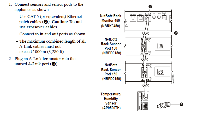
With a NetBotz 450, you can cascade up to a combined total of two NetBotz Rack Sensor Pod 150s
(NBPD0150) and NetBotz Room Sensor Pod 155s (NBPD0155), plus up to a combined total of eight
Temperature Sensors with Digital Display (AP9520T) and Temperature/Humidity Sensors with Digital
Display (AP9520TH).
If possible, please verify if the sensor Pod(NBPD0150) is cascaded as shown below.

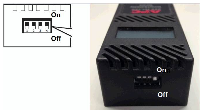
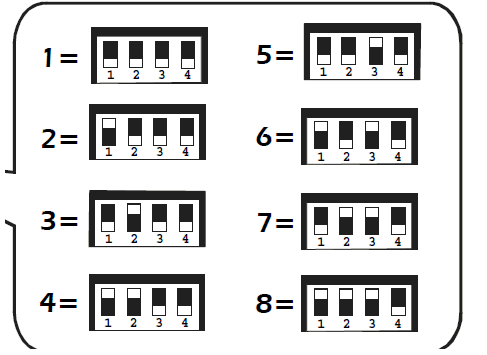
Please also make sure that the device ID is set correctly for the AP9520TH Display sensors. AP9520TH sensor can not decides its ID/Address on the A-Link bus unless we manually set the switch settings.
I think that AP9520TH dipswitches are probably the cause of the problem. I suggest you to follow the guidelines for dipswitch settings that are located in the manual of AP9520TH and make sure that the following is noted:


Make sure that before connecting the sensors that the dipswitches are set. Connecting sensors with the same address will probably cause the sensor not to show correctly.
Make sure that standard Cat5 cables are being used to connect each sensor.
I hope this helps.
Regards,
Bala
(CID:106204723)
Link copied. Please paste this link to share this article on your social media post.
- Mark as New
- Bookmark
- Subscribe
- Mute
- Permalink
- Email to a Friend
- Report Inappropriate Content
Link copied. Please paste this link to share this article on your social media post.
Posted: 2020-07-03 02:54 AM . Last Modified: 2024-04-09 12:08 AM
I checked all the connections of the procedure and settings. Effect is still there. Apparently there is a physical deffekt. The warranty period is over, if the point of having to send checks to the nearest APC service?
(CID:106205317)
Link copied. Please paste this link to share this article on your social media post.
- Mark as New
- Bookmark
- Subscribe
- Mute
- Permalink
- Email to a Friend
- Report Inappropriate Content
Link copied. Please paste this link to share this article on your social media post.
Posted: 2020-07-03 02:54 AM . Last Modified: 2023-10-31 11:24 PM

This question is closed for comments. You're welcome to start a new topic if you have further comments on this issue.
Link copied. Please paste this link to share this article on your social media post.
Create your free account or log in to subscribe to the board - and gain access to more than 10,000+ support articles along with insights from experts and peers.
