
Ask our Experts
Didn't find what you are looking for? Ask our experts!
Share Your Feedback – Help Us Improve Search on Community! Please take a few minutes to participate in our Search Feedback Survey. Your insights will help us deliver the results you need faster and more accurately. Click here to take the survey
Schneider Electric support forum about installation and configuration for DCIM including EcoStruxure IT Expert, IT Advisor, Data Center Expert, and NetBotz
Search in
Link copied. Please paste this link to share this article on your social media post.
Posted: 2020-07-06 12:03 AM . Last Modified: 2024-04-02 11:42 PM
Hi,
I have the task to connect 4-20mA sensors to DCE via NetBotz system.
The problem is that the 4-20mA sensors are connected with a galvanic splitter, it has built-in power supply. The splitter 4-20mA output is powered with 18VDC. The NetBotz 570 4-20mA input has own power supply with 24VDC.
Is there any way to connect 4-20mA sensors from the splitter to the NetBotz 570 4-20mA input?
Gabor
(CID:152568644)
Link copied. Please paste this link to share this article on your social media post.
Link copied. Please paste this link to share this article on your social media post.
Posted: 2020-07-06 12:03 AM . Last Modified: 2024-04-02 11:42 PM
Dear Gabor Novak,
For obvious reasons, the active current output of the Datcon DT1112 U10 I4 I4 splitter cannot be connected to the active current inputs of 4-20 mA NetBotz appliances. Therefore, in your case, you can use a resistive voltage divider with a division factor of 2 together with a cable NBES0305 0...5V. As it should be, I pictured below:
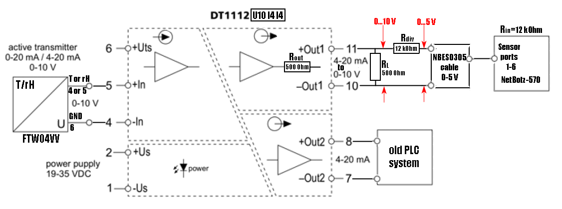
A 500 Ohm load resistor is a converter of current to a voltage of 0...10 V. A resistor Rdiv=12kOhm, together with an input resistance of 12 kOhm of the NetBotz sensor port, creates a voltage divider with a division factor of 2.
The only requirement for this two resistors is accuracy not worse than 1%. Although this inaccuracy can then be compensated in the custom analog sensor setup menu in APC Advanced View.
In addition, you can simplify the solution to your problem using a current to voltage converter with a division factor of 2:
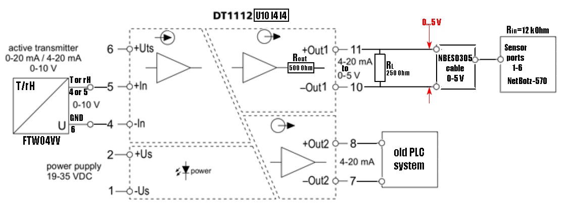
This scheme is simpler and more reliable. But this requires the use of an accurate load resistor with a non-standard resistance value. For the series of resistances E96 (1%), there is only 249 Ohm, and for the series of resistances E192 (0.5%) - 249 Ohm or 252 Ohm.
Again, any measurement inaccuracies can then be compensated in the setup menu of the custom analog sensor in APC Advanced View.
You can also read more about NetBotz sensor ports in topic .
If you have more questions, please ask.
With respect.
(CID:152569127)
Link copied. Please paste this link to share this article on your social media post.
Link copied. Please paste this link to share this article on your social media post.
Posted: 2020-07-06 12:03 AM . Last Modified: 2024-04-02 11:42 PM
Dear Gabor Novak,
It will be very good if you provide a web-link to the datasheet specification for your current galvanic splitter. And then they can help you faster and better 😀.
With respect.
(CID:152568676)
Link copied. Please paste this link to share this article on your social media post.
Link copied. Please paste this link to share this article on your social media post.
Posted: 2020-07-06 12:03 AM . Last Modified: 2024-04-02 11:42 PM
Link copied. Please paste this link to share this article on your social media post.
Link copied. Please paste this link to share this article on your social media post.
Posted: 2020-07-06 12:03 AM . Last Modified: 2024-04-02 11:42 PM
Dear Gabor Novak,
For obvious reasons, the active current output of the Datcon DT1112 U10 I4 I4 splitter cannot be connected to the active current inputs of 4-20 mA NetBotz appliances. Therefore, in your case, you can use a resistive voltage divider with a division factor of 2 together with a cable NBES0305 0...5V. As it should be, I pictured below:
A 500 Ohm load resistor is a converter of current to a voltage of 0...10 V. A resistor Rdiv=12kOhm, together with an input resistance of 12 kOhm of the NetBotz sensor port, creates a voltage divider with a division factor of 2.
The only requirement for this two resistors is accuracy not worse than 1%. Although this inaccuracy can then be compensated in the custom analog sensor setup menu in APC Advanced View.
In addition, you can simplify the solution to your problem using a current to voltage converter with a division factor of 2:
This scheme is simpler and more reliable. But this requires the use of an accurate load resistor with a non-standard resistance value. For the series of resistances E96 (1%), there is only 249 Ohm, and for the series of resistances E192 (0.5%) - 249 Ohm or 252 Ohm.
Again, any measurement inaccuracies can then be compensated in the setup menu of the custom analog sensor in APC Advanced View.
You can also read more about NetBotz sensor ports in topic .
If you have more questions, please ask.
With respect.
(CID:152569127)
Link copied. Please paste this link to share this article on your social media post.
Link copied. Please paste this link to share this article on your social media post.
Posted: 2020-07-06 12:04 AM . Last Modified: 2024-04-02 11:42 PM
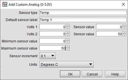
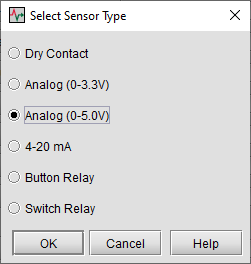
Dear spezialist
I have made the resistive voltage divider with the 0-5 sensor cable. I have connected to the splitter and the NetBotz device. I have configured the custom sensor see the pictures below.
But the temperature reading is not correct. It should be around 20 Celsius.
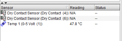
Raw voltage sensor reading
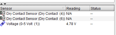
If I look the voltage and the temperature reading it seems to be correct. They correlate to each other.
The problem can be with the resistor value.
Regards,
Gabor
(CID:152569809)
Link copied. Please paste this link to share this article on your social media post.
Link copied. Please paste this link to share this article on your social media post.
Posted: 2020-07-06 12:04 AM . Last Modified: 2024-04-02 11:42 PM
Dear Gabor Novak,
You are right: I assumed that the input impedance of the NetBotz sensor ports is at least ~1 MOhm. As it turned out today from the official answer =SE= technical support, this is not entirely true. Below is very important information on the measurement accuracy and input impedance of the various NetBotz sensor ports.
4-20mA accuracy:
The accuracy of the NBRK0570 will be: +/-2.5% of reading plus +/-1.5% of Full Scale plus the error of the sensor itself. So for example: given a pressure sensor that is 0-100psi and has an accuracy of 1%; if the reading is 80psi, the total possible error would be 2.5% of 80psi + 1.5% of 100psi + 1% of 80psi = 2.0 + 1.5 + 0.8 = +/-4.3 psi.Sensor Ports:
When using dry contact inputs (using NBES0304), they are switching 5 V into 12KOhm +/-0.1% (input impedance) which is 0.42 mA.
The 0-5 VDC input, using NBES0305, is a 12 KOhm +/-0.1% load (input impedance). Accuracy spec: +/-2.5% of reading +/- 10mV.
Unfortunately, I could not find any documentation or standard APC kbase wherever this information was published ☹️.
Therefore, I corrected my previous answer to your question. Please read it again.
With respect.
(CID:152569868)
Link copied. Please paste this link to share this article on your social media post.
Link copied. Please paste this link to share this article on your social media post.
Posted: 2020-07-06 12:04 AM . Last Modified: 2023-10-22 03:11 AM

This question is closed for comments. You're welcome to start a new topic if you have further comments on this issue.
Link copied. Please paste this link to share this article on your social media post.
You’ve reached the end of your document
Create your free account or log in to subscribe to the board - and gain access to more than 10,000+ support articles along with insights from experts and peers.
