Ask our Experts
Didn't find what you are looking for? Ask our experts!
Schneider Electric support forum about installation and configuration for DCIM including EcoStruxure IT Expert, IT Advisor, Data Center Expert, and NetBotz
Search in
Link copied. Please paste this link to share this article on your social media post.
Posted: 2020-07-03 01:26 PM . Last Modified: 2024-04-08 01:37 AM
What is the best way to model an in rack rectifier. I have two similar situations
In both cases there is some DC powered kit in a rack, this is powered by an in rack rectifier. One situation is the rectifier is connect to in rack AC power strips and the other is the rectifier is connected to an AC breaker.
(CID:113641154)
Link copied. Please paste this link to share this article on your social media post.
Link copied. Please paste this link to share this article on your social media post.
Posted: 2020-07-03 01:26 PM . Last Modified: 2024-04-08 01:37 AM
If you want to show it in power path and have its load calculations taken into account, you can model the rectifier as an IT device that gets power from the rack pdu or off of a power panel.
If you are trying to model the DC power path and the devices it powers, thats a different story.
However as of right now, there are some limitation in what you can do with DC power path. it follows all of the same rules as a floor UPS:
(CID:113641300)
Link copied. Please paste this link to share this article on your social media post.
Link copied. Please paste this link to share this article on your social media post.
Posted: 2020-07-03 01:26 PM . Last Modified: 2024-04-08 01:37 AM
Andrew Trabert - So at the moment DCO can't accurately model the situation, can this be caputred as a feature request?
Would you be able to advise what the best model is in DCO for the following;
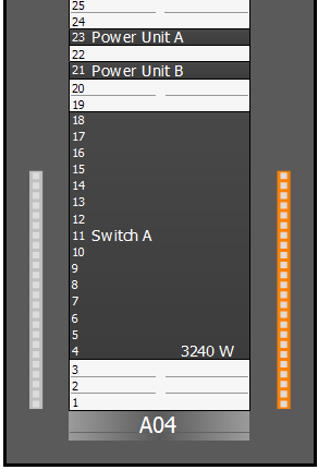
Switch A is powered from Power Unit A & B. Power Unit A is fed from the Orange in rack power strip and Power Unit B from the Grey. The two in rack power strips are connect to a breaker on a power panel.
At the moment it is showing 4 power connections in the rack (giving it double the capacity)

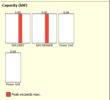
Also there seems to be an error whereas there is 0kW capacity for each unit, even thought the power strips are connected

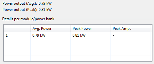
It's also not showing live readings, but I feel that is a seperate issue

(CID:113641529)
Link copied. Please paste this link to share this article on your social media post.
Link copied. Please paste this link to share this article on your social media post.
Posted: 2020-07-03 01:26 PM . Last Modified: 2024-04-08 01:37 AM
correct, its not a 1:1 representation, but it can still be modeled, albeit a little convoluted.
you can't model a rack pdu feeding a rack pdu or rack mount ATS ( DCO also does not support dual fed rack ATS'). You also can't power a device from a different rack.
Model Power unit A/B as generic rack mount equipment, then increase the outlet count in the zero U rack mount power strips so that they equal the number of outlets in both the rack mount power strip and the horizontal power strip -1. Then connect Switch A to the zero U rack mount power strips.
From a power path/capacity perspective, Daisy chaining rack pdus just adds outlets, not power capacity, so this work around still accounts for that. The only thing it doesn't do is include the horizontal power strips in impact analysis.
(CID:113641727)
Link copied. Please paste this link to share this article on your social media post.
Link copied. Please paste this link to share this article on your social media post.
Posted: 2020-07-03 01:26 PM . Last Modified: 2023-10-22 02:17 AM

This question is closed for comments. You're welcome to start a new topic if you have further comments on this issue.
Link copied. Please paste this link to share this article on your social media post.
You’ve reached the end of your document
Create your free account or log in to subscribe to the board - and gain access to more than 10,000+ support articles along with insights from experts and peers.