We Value Your Feedback!
Could you please spare a few minutes to share your thoughts on Cloud Connected vs On-Premise Services. Your feedback can help us shape the future of services.
Learn more about the survey or Click here to Launch the survey
Schneider Electric Services Innovation Team!
Cooling design with vertical grills
EcoStruxure IT forum
Schneider Electric support forum about installation and configuration for DCIM including EcoStruxure IT Expert, IT Advisor, Data Center Expert, and NetBotz
- Mark Topic as New
- Mark Topic as Read
- Float this Topic for Current User
- Bookmark
- Subscribe
- Mute
- Printer Friendly Page
- Mark as New
- Bookmark
- Subscribe
- Mute
- Permalink
- Email to a Friend
- Report Inappropriate Content
Link copied. Please paste this link to share this article on your social media post.
Posted: 2020-07-04 08:36 PM . Last Modified: 2024-04-04 04:07 AM
Cooling design with vertical grills
Hi Team!
Now I'm configuring DCO for our customer.
There is centralized cooling solution on site and air distributed to server room via grilles placed under floor and on the walls.
So I decide to model it with Vertical Grilles.
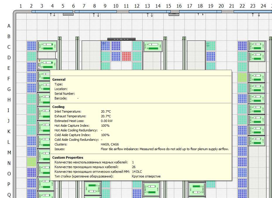
I've place Grilles on the wall, perforated tiles on the floor and set up measured airflow values fot it. It looks cool but I have an issue "Floor tiles imbalance: Measured airflows do not up to floor plenum supply airflow."

And there is message in recommendation tab "There is no perforated tile airflow. Consider adding a CRAC"

What does that mean? Any ideas will be appreciated.
I've tried to play with airflow on wall grilles, but with no luck.
Is there detailed description how our alghoritm works or someone can tell me how to set up such config properly?
(CID:132667817)
- Labels:
-
Data Center Operation
Link copied. Please paste this link to share this article on your social media post.
- Mark as New
- Bookmark
- Subscribe
- Mute
- Permalink
- Email to a Friend
- Report Inappropriate Content
Link copied. Please paste this link to share this article on your social media post.
Posted: 2020-07-04 08:36 PM . Last Modified: 2024-04-04 04:07 AM
Valentin,
Try adding an 'imaginary' CRAC (or several to better model the cold air distribution) outside of the wall where your vertical grills are located, similar to below but with vertical grill for hot air return and no ceiling duct:
Designs with CRAC Units Placed Outside the Room
Also, you may want to leave the vertical grill & perforated floor airflow empty, or at least some of them empty, so DCO can calculate those, based on the CRAC you add , racks etc.
-putting this as comment, to see if anyone else have ideas how to best model this.
Regards,
Chris
(CID:133370395)
Link copied. Please paste this link to share this article on your social media post.
- Mark as New
- Bookmark
- Subscribe
- Mute
- Permalink
- Email to a Friend
- Report Inappropriate Content
Link copied. Please paste this link to share this article on your social media post.
Posted: 2020-07-04 08:36 PM . Last Modified: 2024-04-04 04:07 AM
Hi Cris!
Thanks for your reply!
After series of tests, I've found out that I need to consider raised floor leakage.
So, Supply airflow = Floor tiles airflow + (Floor tiles airflow*Floor leakage).
Drop ceiling leakage is not considered.
I think it's strange that we have no info about how our cooling model works. Because it's important part of capacity planning.
My customer tell me "I know that in row A I have 50 kW electrical power but only 35 kW cooling capacity. How DCO can tell me about that?". And I dont know how to answer...
(CID:133370399)
Link copied. Please paste this link to share this article on your social media post.
- Mark as New
- Bookmark
- Subscribe
- Mute
- Permalink
- Email to a Friend
- Report Inappropriate Content
Link copied. Please paste this link to share this article on your social media post.
Posted: 2020-07-04 08:37 PM . Last Modified: 2024-04-04 04:07 AM
Hi Valentine,
Glad you got that sorted out.
On cooling capacity, the figures in kW is on room level, based on total available CRAC cooling capacity.
Not exactly cooling kW capacity at row/rack, but DCO does provide the breakdown on cooling at rack level using capture index to indicate % cold air (from CRAC) captured by the rack, and % of the rack's hot air captured by CRAC
More info:
-leaving this as comment, let's see what others can add here.
Regards,
Chris
(CID:133370404)
Link copied. Please paste this link to share this article on your social media post.
- Mark as New
- Bookmark
- Subscribe
- Mute
- Permalink
- Email to a Friend
- Report Inappropriate Content
Link copied. Please paste this link to share this article on your social media post.
Posted: 2020-07-04 08:37 PM . Last Modified: 2023-10-20 05:10 AM

This question is closed for comments. You're welcome to start a new topic if you have further comments on this issue.
Link copied. Please paste this link to share this article on your social media post.
Create your free account or log in to subscribe to the board - and gain access to more than 10,000+ support articles along with insights from experts and peers.
This is a heading
With achievable small steps, users progress and continually feel satisfaction in task accomplishment.
Usetiful Onboarding Checklist remembers the progress of every user, allowing them to take bite-sized journeys and continue where they left.
of
