

Ask our Experts
Didn't find what you are looking for? Ask our experts!
Share Your Feedback – Help Us Improve Search on Community! Please take a few minutes to participate in our Search Feedback Survey. Your insights will help us deliver the results you need faster and more accurately. Click here to take the survey
Schneider, APC support forum to share knowledge about installation and configuration for Data Center and Business Power UPSs, Accessories, Software, Services.
Search in
Free
EnglishStrengthen your foundational knowledge in Data Centers for free, enroll in this path today and start your learning journey!
Posted: 2021-07-07 11:42 PM . Last Modified: 2024-02-29 11:47 PM
Link copied. Please paste this link to share this article on your social media post.
Posted: 2021-07-07 11:42 PM . Last Modified: 2024-02-29 11:47 PM
I have an APC SmartUPS SMT3000. The device has batteries from July 2017 and have a charge. The onscreen menu reports there is no input voltage - I've used my voltmeter to check the plug (it's 120V, 30A circuit). Is there any type of fuse or anything I can replace?
Besides the "no input voltage", the device passes self tests and reports the batteries have about 80% capacity. The fan runs, can cycle through the on-screen menu just fine, just can't charge the batteries (and it won't give any output voltage either).
I bought this device from an auction (paid $70 for it) so do not know much history about it. It was supposed to have passed several factory tests, but who knows how valid the sheet was that was in the box.
Any repair options? I live in the midwest.
Link copied. Please paste this link to share this article on your social media post.
Posted: 2021-07-07 11:42 PM . Last Modified: 2024-02-29 11:47 PM
Link copied. Please paste this link to share this article on your social media post.
Posted: 2021-07-07 11:42 PM . Last Modified: 2024-02-29 11:47 PM
I cant see the labelling on the board and I don't know the transformers you talked about in your earlier response that theyre being serviced by one (splited) fuse. But looking at the board there are two onboard transformers. One should be DC powered while the other will be AC powered.
The board working on battery is an indication that the DC onboard transformer is receiving voltage. Check and confirm that the AC powered onboard transformer is receiving voltage.
That transformer powers an IC that tell the UPS that there's online voltage.
Do that check and let me know your findings.
Regards.
Sammie
Link copied. Please paste this link to share this article on your social media post.
Posted: 2021-07-07 11:42 PM . Last Modified: 2024-02-29 11:47 PM
Link copied. Please paste this link to share this article on your social media post.
Posted: 2021-07-07 11:42 PM . Last Modified: 2024-02-29 11:47 PM
If you can, trace the voltage from input and locate where it ends then try to know what's making it end where its ending. On the other hand, check F1 and F2 (fuse) and be sure they're intact. Those fuse sends voltage voltage to T1 and T2 (transformers).
Link copied. Please paste this link to share this article on your social media post.
Posted: 2021-07-07 11:42 PM . Last Modified: 2024-02-29 11:47 PM
Link copied. Please paste this link to share this article on your social media post.
Posted: 2021-07-07 11:42 PM . Last Modified: 2024-02-29 11:47 PM
Any idea where the fuses are located? I found one that is 100A 32V. My voltmeter checks it out ok with the continuity test (i.e. - it beeps when I put a tester on on side and the other side of the fuse). This fuse is for the transformers inside.
This fuse has two black wires that do a y-split and go to each transformer. Assuming this fuse covers both transformers.
I've pulled the large circuit board out and have done a visual inspection. I see a place on the board that talks about using fuses, but there is nothing on the board there.
I've also examined the power supply board (where the electric comes in). It checks out fine and seems to be supplying voltage the the main board.
There is another circuit board that accepts an expansion card. I didn't see any fuses on it. The expansion port should be empty (didn't check but it looks like a "blank" plastic insert is inside of it.)
Schematics would be nice. I know these are not supposed to be user serviceable, but I doubt I have any warranty as I bought this from an auction (and now that I've taken some of the boards out.)
Link copied. Please paste this link to share this article on your social media post.
Posted: 2021-07-07 11:42 PM . Last Modified: 2024-02-29 11:47 PM
Link copied. Please paste this link to share this article on your social media post.
Posted: 2021-07-07 11:42 PM . Last Modified: 2024-02-29 11:47 PM
Send a clear snapshot of the board showing the label of the components let me see if I can explain somethings using the picture.
Link copied. Please paste this link to share this article on your social media post.
Posted: 2021-07-07 11:42 PM . Last Modified: 2024-02-29 11:47 PM
Link copied. Please paste this link to share this article on your social media post.
Posted: 2021-07-07 11:42 PM . Last Modified: 2024-02-29 11:47 PM
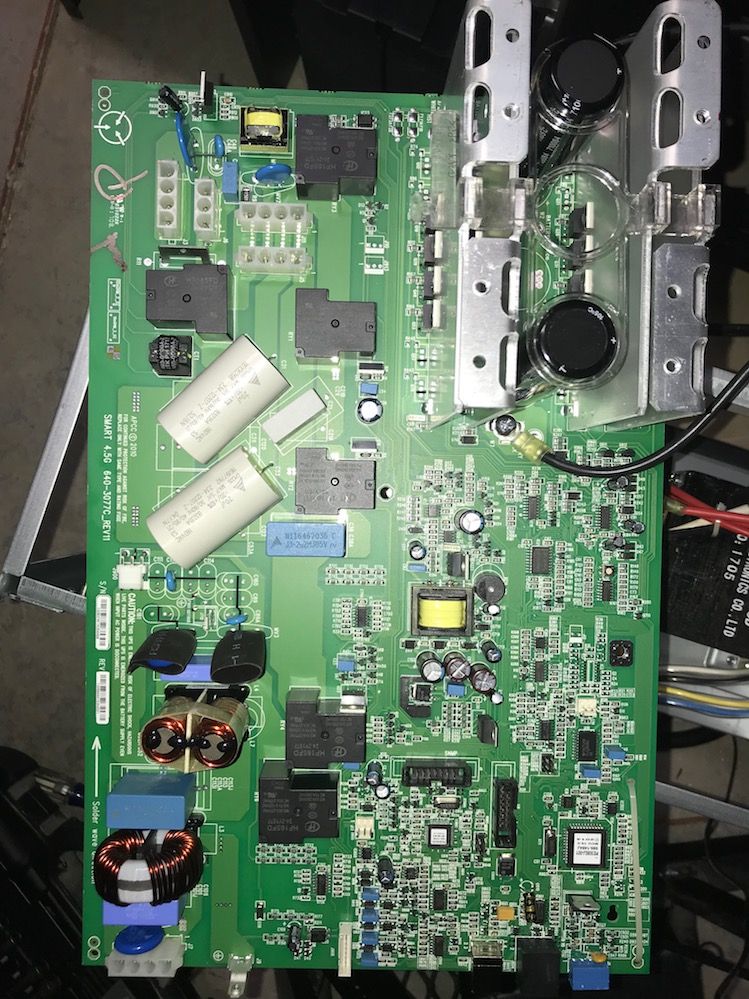
Hopefully this works. I reduced the image size so it could upload. The voltage in starts in the lower left of the circuit board.
Link copied. Please paste this link to share this article on your social media post.
Posted: 2021-07-07 11:42 PM . Last Modified: 2024-02-29 11:47 PM
Link copied. Please paste this link to share this article on your social media post.
Posted: 2021-07-07 11:42 PM . Last Modified: 2024-02-29 11:47 PM
I cant see the labelling on the board and I don't know the transformers you talked about in your earlier response that theyre being serviced by one (splited) fuse. But looking at the board there are two onboard transformers. One should be DC powered while the other will be AC powered.
The board working on battery is an indication that the DC onboard transformer is receiving voltage. Check and confirm that the AC powered onboard transformer is receiving voltage.
That transformer powers an IC that tell the UPS that there's online voltage.
Do that check and let me know your findings.
Regards.
Sammie
Link copied. Please paste this link to share this article on your social media post.
You’ve reached the end of your document
Create your free account or log in to subscribe to the board - and gain access to more than 10,000+ support articles along with insights from experts and peers.
