Ask our Experts
Didn't find what you are looking for? Ask our experts!
Share Your Feedback – Help Us Improve Search on Community! Please take a few minutes to participate in our Search Feedback Survey. Your insights will help us deliver the results you need faster and more accurately. Click here to take the survey
Schneider, APC support forum to share knowledge about installation and configuration for Data Center and Business Power UPSs, Accessories, Software, Services.
Search in
Free
EnglishStrengthen your foundational knowledge in Data Centers for free, enroll in this path today and start your learning journey!
Link copied. Please paste this link to share this article on your social media post.
Posted: 2021-06-28 08:37 AM . Last Modified: 2024-03-17 11:56 PM
Hello,
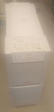
I have an old Smart-UPS 900XLI unit (the one which may be extended with up to 10 external battery packs), serial beginning with S9403, firmware revision is 7TI, circuit board REV7. I'd really appreciate if you could share the factory default constant values for EEPROM registers 0,5,6. Low battery is detected too early, battery constant value probably drifted off far from the original value. Registers 5,6 may be fine, but I'd like to compare against my unit's registers. Interesting experience: this is not the first UPS of this generation that I find with drifted constant values. On this generation of units however, drifting seems to happen only if the DIP switches have been all transferred to the 1 position (and left there for years), and when a calibration tool or management software has been used to alter EEPROM values.
Thanks in advance!

Link copied. Please paste this link to share this article on your social media post.
Link copied. Please paste this link to share this article on your social media post.
Posted: 2021-06-28 08:37 AM . Last Modified: 2024-03-17 11:56 PM
Here is the whole procedure I did:
-soldered a jumper wire to R178 resistor, so it measured 0.0 ohms across its leads
-transferred all of the DIP switches to position 1
-using a terminal emulation program over RS232, I asked for the values of registers 5,6,0 by sending the ASCII values 5,6,0 respectively.
-I kept adjusting register 5 by sending ASCII character 2 as many times as it was needed to cycle to the proper value. (register 0 is adjusted via character 4)
-after reaching the desired value, I confirmed the functionality of the UPS
-turned off the unit, retransferred DIP switches to position 0
-removed the jumper wire from R178
I hope this may be useful to someone.
Link copied. Please paste this link to share this article on your social media post.
Link copied. Please paste this link to share this article on your social media post.
Posted: 2021-06-28 08:37 AM . Last Modified: 2024-03-17 11:56 PM
I have successfully reset the constants to their good (or close to good) values. I happened to have a Smart-UPS 900I (non XL version) around with roughly the same manufacture date and same firmware (7TI). This UPS unit used as a reference had the following values:
5 - F3
6 - FC
0 - 9F
My 900XLI had these:
5 - 9D
6 - FC
0 - A0
I already knew that register 0 is used to determine the available runtime versus battery charge level (ASCII 'f') & load (ASCII 'P'). I had no idea about the other two values. The only difference was register 5, and after correcting it, low battery is no longer detected too early, and battery leds are correctly lit all the way up & lowering slowly as the load depletes the batteries. This makes me believe that register 5 probably determines the battery capacity which is likely calculated somehow using the detected battery voltage.
I did a manual runtime test so that I could accurately set register 0 to display remaining runtime correctly. With new batteries, the 900XLI ran for 88 minutes under ~390W load using 1 external battery pack. The stock '9F' / 'A0' setting was no good for this, it only shows 17 minutes for the given load. I pushed the register 0 value up to 'FE', increasing runtime to 34 minutes, which is still far from the 88 minutes measured manually. Value 'FF' is maximum, but it translates to infinite runtime (>>>> minutes). Concluding all of the above, my final settings are:
5 - F3
6 - FC
0 - FE
I am also inclined to think now (as opposed to my previous post) that these register values do not drift by themselves, at least not in these very old units. Likely the previous owner or a service center attempted to do software calibration and messed up things while doing so.
Link copied. Please paste this link to share this article on your social media post.
Link copied. Please paste this link to share this article on your social media post.
Posted: 2021-06-28 08:37 AM . Last Modified: 2024-03-17 11:56 PM
Here is the whole procedure I did:
-soldered a jumper wire to R178 resistor, so it measured 0.0 ohms across its leads
-transferred all of the DIP switches to position 1
-using a terminal emulation program over RS232, I asked for the values of registers 5,6,0 by sending the ASCII values 5,6,0 respectively.
-I kept adjusting register 5 by sending ASCII character 2 as many times as it was needed to cycle to the proper value. (register 0 is adjusted via character 4)
-after reaching the desired value, I confirmed the functionality of the UPS
-turned off the unit, retransferred DIP switches to position 0
-removed the jumper wire from R178
I hope this may be useful to someone.
Link copied. Please paste this link to share this article on your social media post.
You’ve reached the end of your document
Create your free account or log in to subscribe to the board - and gain access to more than 10,000+ support articles along with insights from experts and peers.