
Ask our Experts
Didn't find what you are looking for? Ask our experts!
Share Your Feedback – Help Us Improve Search on Community! Please take a few minutes to participate in our Search Feedback Survey. Your insights will help us deliver the results you need faster and more accurately. Click here to take the survey
Schneider, APC support forum to share knowledge about installation and configuration for Data Center and Business Power UPSs, Accessories, Software, Services.
Search in
Free
EnglishStrengthen your foundational knowledge in Data Centers for free, enroll in this path today and start your learning journey!
Posted: 2021-07-07 10:18 PM . Last Modified: 2024-03-04 10:49 PM
Link copied. Please paste this link to share this article on your social media post.
Posted: 2021-07-07 10:18 PM . Last Modified: 2024-03-04 10:49 PM
We have had several SYBT5 modules show as failing in the last couple of months, we'd like to be sure they have indeed failed (they have 10 individual batteries inside) before we recycle them and replace the modules. Does anyone know a procedure to reset the module status and force the chassis or software to recognize the batteries as fresh and retest them?
Link copied. Please paste this link to share this article on your social media post.
Link copied. Please paste this link to share this article on your social media post.
Posted: 2021-07-07 10:18 PM . Last Modified: 2024-03-04 10:48 PM
Just wanted to add the following info since it determines which programmer you would need.
the Microcontroller is Microchip PIC16C72A-20/SP http://ww1.microchip.com/downloads/en/DeviceDoc/39016B.pdf
the EEPROM is Microchip 93C66B 4kb 16bit http://ww1.microchip.com/downloads/en/DeviceDoc/21795E.pdf
initially i was going to use an EMP-10 as i had it on hand, however the newer micro's need an adapter which i did not have. (newer than the programmer that is)
Link copied. Please paste this link to share this article on your social media post.
Link copied. Please paste this link to share this article on your social media post.
Posted: 2021-07-07 10:19 PM . Last Modified: 2024-03-04 10:48 PM
just in order to make this post as clear as possible.
all the information on this subject was either in russian or chinese.
the following is a step by step to get this working.
1. locations 64-79 (or in hex: 0xC9-0xF4) need to be zeroed out - this is the location that all errors and issues with the pack are located.
2. locations 50-51 (or in hex: 0xA1, 0xA3) need to be zeroed out - this is the checksum of the eeprom which gets checked to ensure the data is correct.
3. recalculate the checksum. the checksum is calculated from 0x0-0x9F, the rest of the registers 64-79 (or in hex: 0xC9-0xF4) aren't regarded in the calculation.
the checksum needs to be in crc16. in my softwarei had to select the previously mentions address' registers and the checksum was displayed in the bottom of my software.
4. the calculated checksum is reversed in the registers. ex: if your checksum came out to be 0x19EB it would be entered as, EB 19.
in my case 0xA1=EB, 0xA3=19
as long as you calculate the checksum correctly the serial number and date can be anything you want. you know this was successful as the information populates correctly in the web interface of the symmetra.
Link copied. Please paste this link to share this article on your social media post.
Link copied. Please paste this link to share this article on your social media post.
Posted: 2021-07-07 10:22 PM . Last Modified: 2024-03-04 10:46 PM
Yep, I programmed the new chip with the clip. so the wires are correct.
*** EDIT ***
I've found that two of the battery modules I have so far have a DIP socket already in place. I was able to program one in board. the other gave the same issue stuck at verified. If I pull the chip out it programmed fine.
Module Date was 07 on the one that had a socket and I was able to program inboard
Module Date was 08 on the one that had a socket and I couldn't program in board
Module Date was 14 on the direct solder that I couldn't program in board.
Link copied. Please paste this link to share this article on your social media post.
Link copied. Please paste this link to share this article on your social media post.
Posted: 2021-07-07 10:18 PM . Last Modified: 2024-03-04 10:49 PM
I believe the SYBT5 is similar to the SYBT2 in that there is no intelligence in the battery module, just a sense line. If that is the case, you should be able to remove the SYBT5 (if currently installed) by sliding it out a couple of inches, waiting, and reinstalling it. The Symmetra should detect it as a new battery. The initial status should be "good", but you'll want to run a self-test to see if it will operate properly under load. If the self-test passes, you may also want to do a "pull the plug" test to make sure the battery can power the load for a reasonable amount of time. Note that this does have the possibility of dropping power to the connected devices if there is insufficient battery capacity, so bear that in mind.
I prefer to replace all of the batteries in a UPS at the same time - since the charging bus is in parallel across all of the battery modules, it is best if they are all identical models and date code, and at a similar level of charge. Of course, that may not be financially practical in all cases.
I would also suggest putting a sticker with the date of replacement on each battery module, since the UPS only keeps a single "battery replacement date". This way you'll be able to see how old each module is.
I discuss some of my experiences replacing batteries (as opposed to modules) here and here. Needless to say, this isn't supported or recommended by APC.
Link copied. Please paste this link to share this article on your social media post.
Posted: 2021-07-07 10:18 PM . Last Modified: 2024-03-04 10:49 PM
Link copied. Please paste this link to share this article on your social media post.
Posted: 2021-07-07 10:18 PM . Last Modified: 2024-03-04 10:49 PM
Thanks, Terry, for your response. Unfortunately, there is some measure of intelligence in the SYBT5 modules as far as I can discern. Once the unit has been marked as 'failed' for a single battery (even if the other 9 are still viable), you cannot replace the batteries in the chassis and have it work. I tested 10 good batteries, installed them in an SYBT5 module that had failed and the Symmetra UPS still tested them as bad. I even contacted a reseller that sold 10 fresh batteries for the SYBT5 and their reply was "sorry, we haven't figured out a way to reset the module and we meant to take down the item#". I am glad you can replace the batteries in the SYBT2 units but it appears that's not the case with SYBT5 modules. Even APC says that it is not a user serviceable module, you have to replace the whole thing. Guess they were losing money on people buying batteries and repairing the units themselves. Thanks and have a good day!
Link copied. Please paste this link to share this article on your social media post.
Link copied. Please paste this link to share this article on your social media post.
Posted: 2021-07-07 10:18 PM . Last Modified: 2024-03-04 10:49 PM
Yes, SYBT5 has some type of EEPROM in it that keeps track of a few things like battery health, watt hours, etc in it. It is not serviceable by the user as you've found and even our own field engineers don't have access to do it or anything. The entire SYBT5 module is intended to be replaced as you've mentioned.
Link copied. Please paste this link to share this article on your social media post.
Link copied. Please paste this link to share this article on your social media post.
Posted: 2021-07-07 10:18 PM . Last Modified: 2024-03-04 10:49 PM
Oh well... It is a good thing that APC has pushed more intelligence into the battery modules - in the SYBT2, if a single battery goes high-resistance it will heat up and bulge and not be detected. With a microcontroller and EEPROM in there, it can be a lot more effective at determining status and reporting it back to the UPS intelligence module.
Not having any way to reset the failed status is unfortunate. But I expect that most of these units are sold to customers who have service agreements in place. I'm a rather unusual case as I have a pair of Symmetra RM's running in my house (I also have 2 Matrix 5000's and 4 smaller Smart-UPS as well).
If I ever get a Symmetra LX, I'll figure out what's going on and how to reset the status.
Link copied. Please paste this link to share this article on your social media post.
Posted: 2021-07-07 10:18 PM . Last Modified: 2024-03-04 10:49 PM
Link copied. Please paste this link to share this article on your social media post.
Posted: 2021-07-07 10:18 PM . Last Modified: 2024-03-04 10:49 PM
If you ever figure how to do that, please let me and the rest of the world know. According to what the APC folks have posted, even they don't know (or won't explain) how to reset that status when installing new, fresh batteries. I appreciate your posts, Terry, kind regards to you and yours! - mark
Link copied. Please paste this link to share this article on your social media post.
Posted: 2021-07-07 10:18 PM . Last Modified: 2024-03-04 10:49 PM
Link copied. Please paste this link to share this article on your social media post.
Posted: 2021-07-07 10:18 PM . Last Modified: 2024-03-04 10:49 PM
ever figure out how to reset these date codes or any of the smart information?
Link copied. Please paste this link to share this article on your social media post.
Link copied. Please paste this link to share this article on your social media post.
Posted: 2021-07-07 10:18 PM . Last Modified: 2024-03-04 10:49 PM
No, I haven't had any come through for service. I'd need a functioning UPS with one working battery and one bad one.
Link copied. Please paste this link to share this article on your social media post.
Posted: 2021-07-07 10:18 PM . Last Modified: 2024-03-04 10:49 PM
Link copied. Please paste this link to share this article on your social media post.
Posted: 2021-07-07 10:18 PM . Last Modified: 2024-03-04 10:49 PM
On 8/12/2015 6:24 PM, Aram said:ever figure out how to reset these date codes
Remove the EEPROM from the board.
Read the EEPROM with i.e. UP48. Save it (and do backup save). Edit the hex file at address 100090
:10009000310030002F00320031002F0030003800D6 --> This is the original date: October 21 08
Change the hex to:
:10009000310030002F00300037002F0031003500D6 --> The new date is now: October 07 15
Save the the hex file and write to EEPROM. Place EEPROM back into socket (check orientation)
Symmetra LX accepts this change and does not report BATTERY BAD anymore
Link copied. Please paste this link to share this article on your social media post.
Posted: 2021-07-07 10:18 PM . Last Modified: 2024-03-04 10:49 PM
Link copied. Please paste this link to share this article on your social media post.
Posted: 2021-07-07 10:18 PM . Last Modified: 2024-03-04 10:49 PM
Does anyone know how long the modules are good for after the test date on the slip they come with?
Does the countdown start once you mount it in a UPS or are they finite from date of production?
Link copied. Please paste this link to share this article on your social media post.
Link copied. Please paste this link to share this article on your social media post.
Posted: 2021-07-07 10:18 PM . Last Modified: 2024-03-04 10:48 PM
Hi,
We expect batteries to last 3 to 6 years from date of manufacture depending on usage and the environment they are used in.
Link copied. Please paste this link to share this article on your social media post.
Posted: 2021-07-07 10:18 PM . Last Modified: 2024-03-04 10:48 PM
Link copied. Please paste this link to share this article on your social media post.
Posted: 2021-07-07 10:18 PM . Last Modified: 2024-03-04 10:48 PM
How did you find a data map for the contents of the EEPROM? I recently pulled one off of an RS 1300 and it reads fine but I can't find out how to interpret the data.
Link copied. Please paste this link to share this article on your social media post.
Link copied. Please paste this link to share this article on your social media post.
Posted: 2021-07-07 10:18 PM . Last Modified: 2024-03-04 10:48 PM
Just wanted to add the following info since it determines which programmer you would need.
the Microcontroller is Microchip PIC16C72A-20/SP http://ww1.microchip.com/downloads/en/DeviceDoc/39016B.pdf
the EEPROM is Microchip 93C66B 4kb 16bit http://ww1.microchip.com/downloads/en/DeviceDoc/21795E.pdf
initially i was going to use an EMP-10 as i had it on hand, however the newer micro's need an adapter which i did not have. (newer than the programmer that is)
Link copied. Please paste this link to share this article on your social media post.
Link copied. Please paste this link to share this article on your social media post.
Posted: 2021-07-07 10:19 PM . Last Modified: 2024-03-04 10:48 PM
On 8/16/2018 9:39 PM, Walter said:How did you find a data map for the contents of the EEPROM? I recently pulled one off of an RS 1300 and it reads fine but I can't find out how to interpret the data.
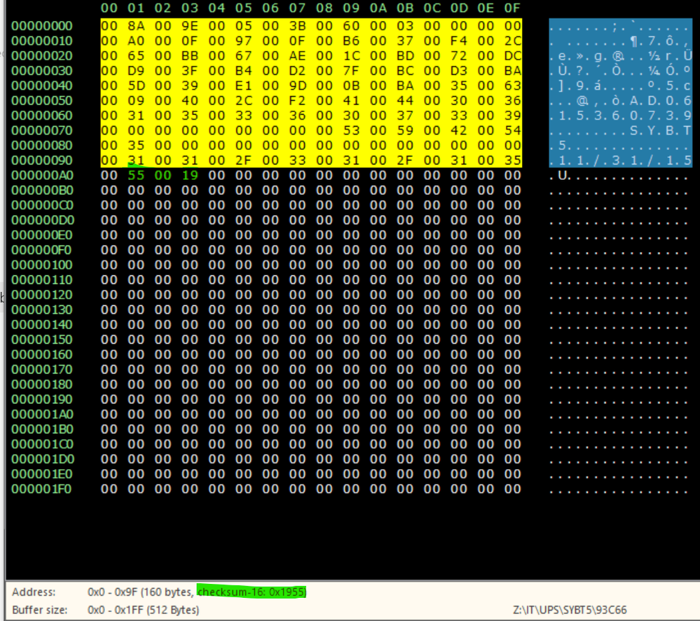
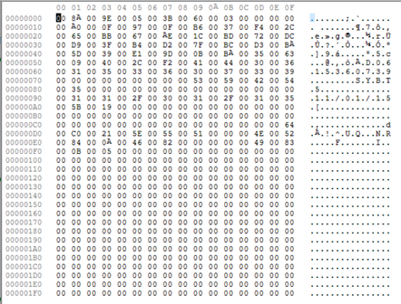
It looks like this in my reader, (REVELPROG IS)
it's fairly easy to see which hex locations it resides in. mine converts to ascii as you can see
Link copied. Please paste this link to share this article on your social media post.
Link copied. Please paste this link to share this article on your social media post.
Posted: 2021-07-07 10:19 PM . Last Modified: 2024-03-04 10:48 PM
just in order to make this post as clear as possible.
all the information on this subject was either in russian or chinese.
the following is a step by step to get this working.
1. locations 64-79 (or in hex: 0xC9-0xF4) need to be zeroed out - this is the location that all errors and issues with the pack are located.
2. locations 50-51 (or in hex: 0xA1, 0xA3) need to be zeroed out - this is the checksum of the eeprom which gets checked to ensure the data is correct.
3. recalculate the checksum. the checksum is calculated from 0x0-0x9F, the rest of the registers 64-79 (or in hex: 0xC9-0xF4) aren't regarded in the calculation.
the checksum needs to be in crc16. in my softwarei had to select the previously mentions address' registers and the checksum was displayed in the bottom of my software.
4. the calculated checksum is reversed in the registers. ex: if your checksum came out to be 0x19EB it would be entered as, EB 19.
in my case 0xA1=EB, 0xA3=19
as long as you calculate the checksum correctly the serial number and date can be anything you want. you know this was successful as the information populates correctly in the web interface of the symmetra.
Link copied. Please paste this link to share this article on your social media post.
Link copied. Please paste this link to share this article on your social media post.
Posted: 2021-07-07 10:19 PM . Last Modified: 2024-03-04 10:48 PM
Tal,
Thank you. This post has been very helpful.
Can you provide the CRC-16 Algorithm that was used for the Checksum?
i.e. CRC-16/CCITT-FALSE, CRC-16/ARC, CRC-16/BUYPASS, more and more and more.............
or better yet, can you please provide the data from your 0x0-0x9F registers that resulted in your CRC-16 result of "0x-19EB" and I can put it into my CRC calculator and figure out which one to use.
The 0x0-0x9f register values (see below) from your screen capture do not seem to provide a CRC-16 result of 0x19EB when I use the CRC-16 Calculator at this link: https://crccalc.com/
00 8a 00 9e 00 05 00 3b 00 60 00 03 00 00 00 00
00 a0 00 0f 00 97 00 0f 00 b6 00 37 00 f4 00 2c
00 65 00 bb 00 67 00 ae 00 1c 00 bd 00 72 00 dc
00 d9 00 3f 00 b4 00 d2 00 7f 00 bc 00 d3 00 ba
00 5d 00 39 00 e1 00 9d 00 0b 00 ba 00 35 00 63
00 09 00 40 00 2c 00 f2 00 41 00 44 00 30 00 36
00 31 00 35 00 33 00 36 00 30 00 37 00 33 00 39
00 00 00 00 00 00 00 00 00 53 00 59 00 42 00 54
00 35 00 00 00 00 00 00 00 00 00 00 00 00 00 00
00 31 00 31 00 2f 00 30 00 31 00 2f 00 31 00 35
Best,
Jonathan
Link copied. Please paste this link to share this article on your social media post.
Link copied. Please paste this link to share this article on your social media post.
Link copied. Please paste this link to share this article on your social media post.
Link copied. Please paste this link to share this article on your social media post.
Posted: 2021-07-07 10:19 PM . Last Modified: 2024-03-04 10:48 PM
Tal,
Thank you so much for providing that output.
I can now see that the checksum required is simply the accumulation (HEX adding) of all the HEX vales in the 0x00 - 0x9f registers.
00+8a+00+9e+00+05+........+00+09+00+40+00+2c+....+00+31+00+35 = 0x1955
Best,
Jonathan
Link copied. Please paste this link to share this article on your social media post.
Link copied. Please paste this link to share this article on your social media post.
Posted: 2021-07-07 10:19 PM . Last Modified: 2024-03-04 10:48 PM
Thank you both!
Link copied. Please paste this link to share this article on your social media post.
Link copied. Please paste this link to share this article on your social media post.
Posted: 2021-07-07 10:19 PM . Last Modified: 2024-03-04 10:48 PM
Tal,
Do you recommend clearing out all of the values in registers 0x0a004 - 0x1f00f?
Best,
Jonathan
Link copied. Please paste this link to share this article on your social media post.
Link copied. Please paste this link to share this article on your social media post.
Posted: 2021-07-07 10:19 PM . Last Modified: 2024-03-04 10:48 PM
Yes,
Those are where the error codes are saved as well as charge data.
After changing the batteries I usually do a full charge calibration and it repopulates the correct info for the pack.
Link copied. Please paste this link to share this article on your social media post.
Link copied. Please paste this link to share this article on your social media post.
Posted: 2021-07-07 10:19 PM . Last Modified: 2024-03-04 10:48 PM
Tal,
Thank you. This has been working like a charm with the 10+ battery packs that we have. It feels good to save all that $$$.
Best,
Jonathan
Link copied. Please paste this link to share this article on your social media post.
Posted: 2021-07-07 10:20 PM . Last Modified: 2024-03-04 10:48 PM
Link copied. Please paste this link to share this article on your social media post.
Posted: 2021-07-07 10:20 PM . Last Modified: 2024-03-04 10:48 PM
Couple questions:
I don't have a unit in front of me; is this the correct part? https://www.digikey.com/product-detail/en/93C66B-I%2fP/93C66B-I%2fP-ND/572371/?itemSeq=318268608
Do you recommend this or another programmer?https://www.reveltronics.com/en/shop/18/7/chip-programmers/revelprog-is-serial-device-eeprom-flash-p...
Or... are you interested perhaps in providing a service of re-programming EEPROMS for some of us? I have the EE background to do it, but can't really justify the time expenditure to do so. I tried buying completely new battery assemblies last time but out of five I ordered, four arrived with hidden shipping damage because APC failed to consider what happens when the cartons are dropped even a short distance on their ends. It took weeks and multiple re-shipments to get it resolved. I'd rather just replace the individual batteries and drop in a reprogrammed chip.
Link copied. Please paste this link to share this article on your social media post.
Link copied. Please paste this link to share this article on your social media post.
Posted: 2021-07-07 10:20 PM . Last Modified: 2024-03-04 10:48 PM
Yes that's the correct eeprom.
I'd recommend buying a pair of chip removal tweezers too. It helps the pins not get bent when removing the old chips.
For the programmer I used that one. I found it to be the best interface and hardware for the cost.
What I've done is saved a copy of each dump for every pack based on its s/n that's all good to go. Then I usually load it and set the correct replacement date and update the checksum and then burn it to a new eeprom. If it's an original chip then I replace it with a new one and take the original out of circulation. I'll swap out the eeproms with another from the pack each time I have to replace batteries.
I recommend the Yuasa NPX35's I've found them to be a bit better than the original apc batteries.
They also don't expand when they get old.
I'd shy away from any paid service. Don't need the legal implications of that for the few bucks I'd make.
The Knowledge is free and takes less than 2 minutes to do. And you'll make a profit on the first battery swap even with the cost of the programmer.
Link copied. Please paste this link to share this article on your social media post.
Posted: 2021-07-07 10:20 PM . Last Modified: 2024-03-04 10:48 PM
Link copied. Please paste this link to share this article on your social media post.
Posted: 2021-07-07 10:20 PM . Last Modified: 2024-03-04 10:48 PM
Tal - Thanks, for the super quick response. I guess I will go ahead and do it.
I have had decent luck with Powersonic PSH-1280FR (note, PSH not PS) and most recently with CSB HRL-1234W (HRL not HR).
I considered Yuasa last time but other than in my motorcycle, haven't used them, and they recently became EnerSys. Also their wattage/cell specs are just a smidgen lower than the CSB at the relevant discharge rates. I can share a comparison chart if anyone wants, but paper specs don't always translate to performance AND say nothing about how they age. In fact, when used in long strings like APC does, their ability to stay matched over time may be more important than anything and is not spec'd at all.
Link copied. Please paste this link to share this article on your social media post.
Link copied. Please paste this link to share this article on your social media post.
Posted: 2021-07-07 10:20 PM . Last Modified: 2024-03-04 10:48 PM
Jeremy,
I have had great success programming the 93c66b chips with the EZP2010 programmer. My AV program saw some kind of impeded Trogan in the driver, so I just ran it on an air-gaped PC.
We get all of our replacement batteries from BattteyMart.com (You will need Qty 10 of Part Number SLA-12V9-F2 12v9.0Ah/20HR for each tray)
I would also recommend a de-soldering tool if you do not have one, they seem to work much better than an iron and a solder sucker.
Good Luck!
Jonathan
Link copied. Please paste this link to share this article on your social media post.
Posted: 2021-07-07 10:20 PM . Last Modified: 2024-03-04 10:48 PM
Link copied. Please paste this link to share this article on your social media post.
Posted: 2021-07-07 10:20 PM . Last Modified: 2024-03-04 10:48 PM
I purchased a RevelProg IS and am happy with it. It makes it pretty simple to reprogram the date etc, other than the minor hassle of needing to unsolder the EEPROM and install a socket (something I am very experienced at, so no biggie). BUT, I am curious if anyone has attempted in-circuit programming of these? In theory it is doable.
I am also curious if anyone knows what the first 8 bytes of the EEPROM do. They seem to vary from chip to chip across the batteries I have checked.
Thx to all of you
Jeremy
Link copied. Please paste this link to share this article on your social media post.
Posted: 2021-07-07 10:20 PM . Last Modified: 2024-03-04 10:47 PM
Link copied. Please paste this link to share this article on your social media post.
Posted: 2021-07-07 10:20 PM . Last Modified: 2024-03-04 10:47 PM
Same issue over here, I'm actually getting my EEPROM taken off my SYBT5 module by a 3rd party. then reprogramming the chip myself. Hoping that RevelProg IS works for me! I'll update with how my exp goes
Link copied. Please paste this link to share this article on your social media post.
Posted: 2021-07-07 10:20 PM . Last Modified: 2024-03-04 10:47 PM
Link copied. Please paste this link to share this article on your social media post.
Posted: 2021-07-07 10:20 PM . Last Modified: 2024-03-04 10:47 PM
Interesting timing - I am getting ready to see if I can reprogram the chip without removing it. I'll report back.
Link copied. Please paste this link to share this article on your social media post.
Link copied. Please paste this link to share this article on your social media post.
Posted: 2021-07-07 10:20 PM . Last Modified: 2024-03-04 10:47 PM
If you are having a 3rd party remove the EEPROM, consider having them add a socket for the EEPROM to the board so that the EEPROM can be removed more easier in the future, if needed.
Link copied. Please paste this link to share this article on your social media post.
Posted: 2021-07-07 10:20 PM . Last Modified: 2024-03-04 10:47 PM
Link copied. Please paste this link to share this article on your social media post.
Posted: 2021-07-07 10:20 PM . Last Modified: 2024-03-04 10:47 PM
haha wow that is odd timing, please let me know how it goes. If i can reprogram without removal then that would be much more cost effective
Link copied. Please paste this link to share this article on your social media post.
Posted: 2021-07-07 10:20 PM . Last Modified: 2024-03-04 10:47 PM
Link copied. Please paste this link to share this article on your social media post.
Posted: 2021-07-07 10:20 PM . Last Modified: 2024-03-04 10:47 PM
Great News! I just successfully programmed a chip on the board without removing it! I used a DIP Test clip connected to the Reveltronics programmer. This makes things vastly easier. Now...why didn't I do this test before I unsoldered the chips and added sockets to 23 out of the 26 trays I have?
All you need is the clip below. Note, it is a DIP clip, not SOIC. The Reveltronic already comes with the wire harness that you connect to the clip.
https://www.digikey.com/product-detail/en/923739-08/923739-08-ND/12078
Pinout details: Wire #1 of the harness (black wire) goes to pin one of the clip (the one that contacts pin one of the chip, denoted by a molded dot on the chip), wire #2 goes to the adjacent pin, and you work your way around counter-clockwise looking down at the chip until you finish opposite where you started with wire 8 (orange). The two remaining wires (red and brown) are not used. I can send a photo if needed.
Link copied. Please paste this link to share this article on your social media post.
Link copied. Please paste this link to share this article on your social media post.
Posted: 2021-07-07 10:20 PM . Last Modified: 2024-03-04 10:47 PM
That's great news!
The sybt5 comes in an smt soic version as well as a standard 8 pin dip. The older version that I have uses the 8 pin dip sockets which are removable.
I just wanted to mention that as it depends on the date of manufacture. Considering I much prefer taking them out and programming at my desk it's vastly better having the chips be removable.
Link copied. Please paste this link to share this article on your social media post.
Posted: 2021-07-07 10:20 PM . Last Modified: 2024-03-04 10:47 PM
Link copied. Please paste this link to share this article on your social media post.
Posted: 2021-07-07 10:20 PM . Last Modified: 2024-03-04 10:47 PM
To be honest, im about as green as a farmers thumb when it comes to this stuff. Im by no means a programmer so that's why i was hoping for at least some understanding. a photo would probably help! I'm trying to find some sources to really get a good idea of how i plan on going about reprogramming my chip. But i guess if i can get this i can chalk it up as a huge accomplishment! haha
Link copied. Please paste this link to share this article on your social media post.
Posted: 2021-07-07 10:20 PM . Last Modified: 2024-03-04 10:47 PM
Link copied. Please paste this link to share this article on your social media post.
Posted: 2021-07-07 10:20 PM . Last Modified: 2024-03-04 10:47 PM
Separate issue: The rebuilding of the trays is non-trivial IF you want to guarantee a reliable system. You need to remove the wires carefully or you will damage the springiness of the "Faston" slip-on terminals that are crimped to the wires. APC uses ones with a plastic slider sleeve. The sleeve actually actuates an internal locking mechanism. To remove a wire, you have to pull on the sleeve, not the wire. Pulling on the sleeve internally depresses a locking tab that grips the hole in the battery terminal. If you just yank on the wire the tab will stick and you will end up deforming the spring-brass piece that presses against the battery terminal. You can do some limited reforming of the terminal with pliers, but if it won't grip properly you need to cut off and replace the terminal. ALSO note, after you slide the wire onto the battery terminal, it's a good idea to push the plastic shroud towards the terminal to make sure it isn't pressing backwards against the internal release tab. That will help it grip.
Also it's a good idea to have a supply of replacement screws in case any are stripped. At under $3.00 for qty 100 with free shipping, they're a bargain.
https://www.amazon.com/gp/product/B000MN3HEQ
Link copied. Please paste this link to share this article on your social media post.
Posted: 2021-07-07 10:20 PM . Last Modified: 2024-03-04 10:47 PM
Link copied. Please paste this link to share this article on your social media post.
Posted: 2021-07-07 10:20 PM . Last Modified: 2024-03-04 10:47 PM
Interesting. I recently bought a new SYBT5 that is dated late 2019 and it had a soldered-in 8-pin DIP.
REQUEST 1: I am still in search of the meaning of bytes 1, 3, 5, 7. Does anybody know what they are for? I have 9 trays that came from rebuilders who had substituted blank eeproms (they actually will work that way, but not perfectly) and I would like to recreate what should be there. Inspecting 16 good ones reveals that bytes 1 and 3 are unique for each tray as are the lower 4-bits of byte 5. The upper half of byte 5 is always either 0 or F. If it's a 0 then byte 7 is always 3B. If it's an F then byte 7 is 3B. Beyond that I have not been able to decode them. HELP...
REQUEST 2: I have been able to decode some but not all of the data fields displayed by the UPS management card or console. Does anyone know these fields well?
Link copied. Please paste this link to share this article on your social media post.
Posted: 2021-07-07 10:20 PM . Last Modified: 2024-03-04 10:47 PM
Link copied. Please paste this link to share this article on your social media post.
Posted: 2021-07-07 10:20 PM . Last Modified: 2024-03-04 10:47 PM
My boss said he will be the one to de-solder the chip and buy the revelprog-IS. So basically, now i need to get an understanding for the byte codes etc. I was looking at the previous posts but if anyone can help me with the breakdown of the modifications or heck if i see the backup pic vs the updated pic codes i can decode them myself and see where the modifications of my chip need to take place. I'd rather not tell my boss everything is clear for him to solder the chip back on then whoop i put the wrong values in!... back to square 1... haha
Link copied. Please paste this link to share this article on your social media post.
Link copied. Please paste this link to share this article on your social media post.
Posted: 2021-07-07 10:21 PM . Last Modified: 2024-03-04 10:47 PM
My post on the second page of this thread is quite detailed. That's pretty much everything you need to do in order to get it working.
Link copied. Please paste this link to share this article on your social media post.
Link copied. Please paste this link to share this article on your social media post.
Posted: 2021-07-07 10:21 PM . Last Modified: 2024-03-04 10:47 PM
My guess is that it's the assembly line / builders info and calibration certification. I haven't seen it update on mine ever. I have 11 sybt5 packs.
Link copied. Please paste this link to share this article on your social media post.
Posted: 2021-07-07 10:21 PM . Last Modified: 2024-03-04 10:47 PM
Link copied. Please paste this link to share this article on your social media post.
Posted: 2021-07-07 10:21 PM . Last Modified: 2024-03-04 10:47 PM
Tal,
Thx. Any chance you have the contents avail for those bytes (0x01, 0x03, 0x05, 0x07)? I am looking across as many as I can to try to sleuth out any meaning.
Link copied. Please paste this link to share this article on your social media post.
Posted: 2021-07-07 10:21 PM . Last Modified: 2024-03-04 10:47 PM
Link copied. Please paste this link to share this article on your social media post.
Posted: 2021-07-07 10:21 PM . Last Modified: 2024-03-04 10:47 PM
Aaron,
If you are buying new chips you definitely should solder in a socket instead of the chip. The ones I recommend are below. At $0.50 each they are a trivial cost. They are also a design known to be reliable (IC socket reliability is a topic I dealt with professionally long long ago). And shipping from DigiKey is cheap for small packages, as they send them 1st Class USPS.
https://www.digikey.com/product-detail/en/3m/4808-3000-CP/3M5461-ND/1133614
HOWEVER - if you use the approach I described of programming them in-place you avoid all the hassle of unsoldering (and the damage risk if you are not skilled at it) AND you don't have to buy chips or sockets.
P.S. If for any reason you need more of the rubber bumpers (i.e. someone threw them out with the old batteries by mistake), DigiKey has those too:
https://www.digikey.com/product-detail/en/3m/SJ-5514-(BLACK)/SJ5514-0-ND/102591
Link copied. Please paste this link to share this article on your social media post.
Link copied. Please paste this link to share this article on your social media post.
Posted: 2021-07-07 10:21 PM . Last Modified: 2024-03-04 10:47 PM
I can send you the raw bin files. I have the untouched dumps for 12 packs.
Having replacement bumpers and screws is a great idea!
Link copied. Please paste this link to share this article on your social media post.
Posted: 2021-07-07 10:21 PM . Last Modified: 2024-03-04 10:47 PM
Link copied. Please paste this link to share this article on your social media post.
Posted: 2021-07-07 10:21 PM . Last Modified: 2024-03-04 10:47 PM
Hey Jeremy,
I went ahead and bought a REVELPROG-IS straight from Reveltronics, should be in sometime next week. I'll let you know if i manage to learn something new! haha
Link copied. Please paste this link to share this article on your social media post.
Posted: 2021-07-07 10:21 PM . Last Modified: 2024-03-04 10:47 PM
Link copied. Please paste this link to share this article on your social media post.
Posted: 2021-07-07 10:21 PM . Last Modified: 2024-03-04 10:47 PM
Thanks Tal, I appreciate it! I might just go by the previous posts though. Hopefully it is as straightforward as you guys make it!
Link copied. Please paste this link to share this article on your social media post.
Link copied. Please paste this link to share this article on your social media post.
Posted: 2021-07-07 10:21 PM . Last Modified: 2024-03-04 10:47 PM
Jeremy,
I Sent you an email with the bin files for all my sybt5's.
Link copied. Please paste this link to share this article on your social media post.
Posted: 2021-07-07 10:21 PM . Last Modified: 2024-03-04 10:46 PM
Link copied. Please paste this link to share this article on your social media post.
Posted: 2021-07-07 10:21 PM . Last Modified: 2024-03-04 10:46 PM
Hi Jeremy,
That is great news. I have been trying to program the eeprom in circuit without any success. Needless to say, I might not be using the correct programmer. I have ordered the REVELPROG IS as I believe that is the same one you are using. Would you be willing to share some information on the exact procedure you followed to reprogram the EEPROM. Some photos would be very helpful, especially the cable connection between the programmer and the test clip. Do you use the serial port on the programmer or the ZIF socket? Have you had any issues determining the correct checksum.
Regards
Francois
On 5/12/2020 4:32 PM, Jeremy said:Pinout details: Wire #1 of the harness (black wire) goes to pin one of the clip (the one that contacts pin one of the chip, denoted by a molded dot on the chip), wire #2 goes to the adjacent pin, and you work your way around counter-clockwise looking down at the chip until you finish opposite where you started with wire 8 (orange). The two remaining wires (red and brown) are not used. I can send a photo if needed.
Link copied. Please paste this link to share this article on your social media post.
Link copied. Please paste this link to share this article on your social media post.
Posted: 2021-07-07 10:21 PM . Last Modified: 2024-03-04 10:46 PM
Hey guys, Trying to do this myself and I too have never worked with programming.
I purchased the Revelprog IS and the 3M Chip Clip
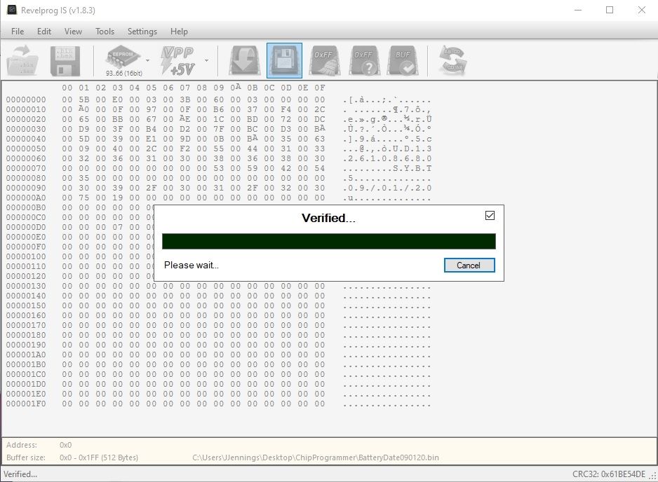
I was able to read the chip, edit the locations and now I'm stuck writing back to the chip.
The programmer is stuck at "verified Please wait..." How long should this step take? it's been about 10 minutes.
Link copied. Please paste this link to share this article on your social media post.
Posted: 2021-07-07 10:21 PM . Last Modified: 2024-03-04 10:46 PM
Link copied. Please paste this link to share this article on your social media post.
Posted: 2021-07-07 10:21 PM . Last Modified: 2024-03-04 10:46 PM
Hi Justin,
I am still waiting on my programmer so I am not a 100% sure. I assume it shouldn't take that long.
Maybe you should try to put the original dump back.
Are there any experts still on this thread that can help us out?
Link copied. Please paste this link to share this article on your social media post.
Link copied. Please paste this link to share this article on your social media post.
Posted: 2021-07-07 10:22 PM . Last Modified: 2024-03-04 10:46 PM
the verification stage should be about 5 seconds tops.
if it's not verifying it's possible that you should either desolder the chip or replace it entirely.
i typically recommend keeping spare chips on hand. is it a tiny SOIC chip or is it a larger DIP style package?
Link copied. Please paste this link to share this article on your social media post.
Posted: 2021-07-07 10:22 PM . Last Modified: 2024-03-04 10:46 PM
Link copied. Please paste this link to share this article on your social media post.
Posted: 2021-07-07 10:22 PM . Last Modified: 2024-03-04 10:46 PM
If you were able to read it initially then it should have verified in about the same length of time. I'd restart the app and try reading it. If the read matches what you wanted, then you are okay.
I'll think on it a bit to see if I can think up any weird issues. Can you confirm the pin-mapping of your clip setup?
Link copied. Please paste this link to share this article on your social media post.
You’ve reached the end of your document
Create your free account or log in to subscribe to the board - and gain access to more than 10,000+ support articles along with insights from experts and peers.
