
Ask our Experts
Didn't find what you are looking for? Ask our experts!
Share Your Feedback – Help Us Improve Search on Community! Please take a few minutes to participate in our Search Feedback Survey. Your insights will help us deliver the results you need faster and more accurately. Click here to take the survey
Schneider Electric support forum about installation and configuration for DCIM including EcoStruxure IT Expert, IT Advisor, Data Center Expert, and NetBotz
Search in
Link copied. Please paste this link to share this article on your social media post.
Posted: 2020-07-04 10:02 PM . Last Modified: 2024-04-04 03:28 AM
Looking for some advice on how to correctly model a power setup.
There is one LV input that has a separate feed to two UPS units A and B.
The two UPS's output on to a common busbar which in turns connects to three separate floor PDUs. Rack power strips are then connected to the floor PDUs.
I have currently modelled this in DCO as follows,
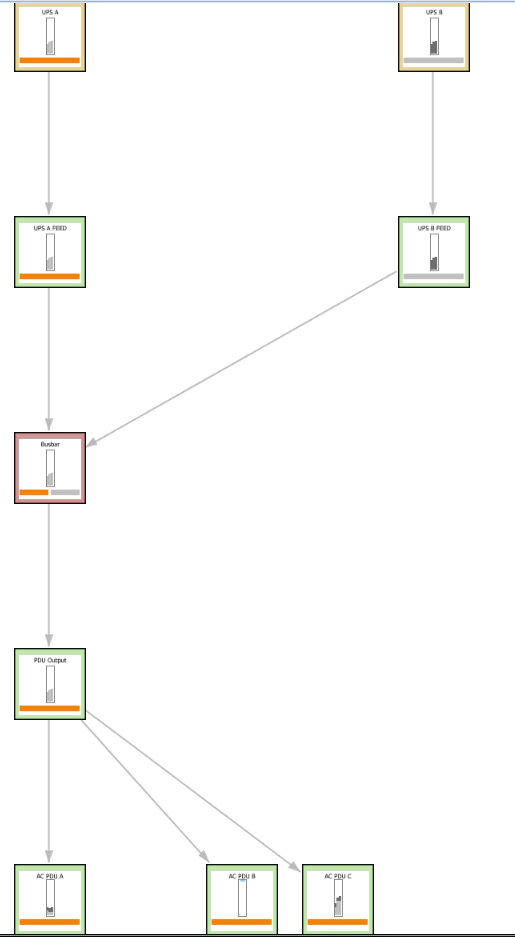
I then have rack power strips connected to the relevant breakers in the floor PDUs with in rack device redundancy set to DN+1.
Is this correct?
(CID:133374306)
Link copied. Please paste this link to share this article on your social media post.
Link copied. Please paste this link to share this article on your social media post.
Posted: 2020-07-04 10:02 PM . Last Modified: 2024-04-04 03:28 AM
Hi James,
I think it depends on UPS internal redundancy settings.
a) If UPS internal redundancy is N+1, then the rack device redundancy may be
Distribution redundancy N+1 (if connected to two rack pdus)
or N+1 (if connected to one rack pdu)
b) If UPS internal redundancy is N, then the rack device redundancy may be
Distribution redundancy N (if connected to two rack pdus)
or N (if connected to one rack pdu).
Kind regards
(CID:133374377)
Link copied. Please paste this link to share this article on your social media post.
Link copied. Please paste this link to share this article on your social media post.
Posted: 2020-07-04 10:02 PM . Last Modified: 2024-04-04 03:28 AM
Jef Faridi - Thanks for the reply. There are two rack power strips per rack with each device connect to both. Aside from the redundancy of the in rack devices is the general power path correct? Or is there a better way to represent it?
(CID:133374398)
Link copied. Please paste this link to share this article on your social media post.
Link copied. Please paste this link to share this article on your social media post.
Posted: 2020-07-04 10:02 PM . Last Modified: 2024-04-04 03:28 AM
Hi James,
I have restudied the description, I don't think connecting two power sources (UPS A and B) to Busbar (apparently ats/sts device) is supported in DCO.
I think the best workaround could be only connect one UPS to Busbar (modeled as PDU), and increase the UPS capacity to the total available capacity (UPS A + UPS B).
Kind regards
(CID:133374852)
Link copied. Please paste this link to share this article on your social media post.
Link copied. Please paste this link to share this article on your social media post.
Posted: 2020-07-04 10:02 PM . Last Modified: 2024-04-04 03:28 AM
Hi James,
General speaking, a given power infrastructure can be utilized in different ways, which is why DCO has additional settings on UPS, rack, server, etc; they are there so you can tell DCO how you intend to utilized your power infrastructure.
Which means, for a given setup there is not just one correct setting, it all boils down to what you want to active.
So, when you are asking if your the setup is correct, the answer is going to be: yes AND no, it depends on why the power infrastructure is designed this way, that is, how do you intend to utilized it?
A1) Considering the 2 UPS's connected to a busbar, normally this means that they work in parallel and both shares the load. Do you intend to use the full capacity of the 2 UPS's or is it a redundancy setup where one UPS should be able to handle the entire load?
A2) Does the 2 UPS's have internal redundancy, e.g. some =SE= UPS's has a number of power modules where one can be considered as redundant.
B) Why are there 2 rackPDUs in the rack, is it because you need more power capacity in the rack than one rackPDU can deliver? Or is it because you want redundancy at rackPDU level, i.e. one rackPDU is enough to power all equipment in the rack?
Once you have answered these questions we (Jeff or me) can come up with some recommendations on how to model/configure your power path in DCO.
Best,
Gert
(CID:133375572)
Link copied. Please paste this link to share this article on your social media post.
Link copied. Please paste this link to share this article on your social media post.
Posted: 2020-07-04 10:03 PM . Last Modified: 2024-04-04 03:28 AM
Gert Lehmann - To answer your questions
A1 - They are intended to be used in a redundant setup. One UPS should be able to take the whole load.
A2 - There is no internal redundancy in the 2 UPS's
B - This is for redundancy at rack level - each device is connected to both rack PDUs.
(CID:133375639)
Link copied. Please paste this link to share this article on your social media post.
Link copied. Please paste this link to share this article on your social media post.
Posted: 2020-07-04 10:03 PM . Last Modified: 2024-04-04 03:28 AM
OK, in that case I would recommend the following:
A) DCO is not able to model busbar/parallel-ups and the normal "work around" is to model just one UPS with N+1 and specifying the capacity without the "+1" UPS - e.g. if you have 2 x 1 MW then then capacity is 1 MW.
Since there are only 2 UPS's, your setup with an ATS would also work, but it that case the UPS redundancy would be N (since you have modeled the "+1" using an ATS) and each UPS should have their full capacity (e.g. 1 MW each).
B) The "Infrastructure requirements redundancy" on equipment in the racks should be "DN+1" if you setup the UPS as "N+1", otherwise is should be "DN" - the reason I asked is beacsue people has a tendency to connect devices to both rackPDUs even when they want to utilize the full capacity (N).
Best,
Gert
(CID:133375912)
Link copied. Please paste this link to share this article on your social media post.
Link copied. Please paste this link to share this article on your social media post.
Posted: 2020-07-04 10:03 PM . Last Modified: 2023-10-22 01:07 AM

This question is closed for comments. You're welcome to start a new topic if you have further comments on this issue.
Link copied. Please paste this link to share this article on your social media post.
You’ve reached the end of your document
Create your free account or log in to subscribe to the board - and gain access to more than 10,000+ support articles along with insights from experts and peers.
