Help
  • Explore Community
  • Get Started
  • Ask the Community
  • How-To & Best Practices
  • Contact Support
Notifications
Login / Register
Community
Community
Notifications
close
  • Forums
  • Knowledge Center
  • Events & Webinars
  • Ideas
  • Blogs
Help
Help
  • Explore Community
  • Get Started
  • Ask the Community
  • How-To & Best Practices
  • Contact Support
Login / Register
Sustainability
Sustainability

Join our "Ask Me About" community webinar on May 20th at 9 AM CET and 5 PM CET to explore cybersecurity and monitoring for Data Center and edge IT. Learn about market trends, cutting-edge technologies, and best practices from industry experts.
Register and secure your Critical IT infrastructure

How do I read the feedback voltage from a DuraDrive actuator (MS4x / MS5x series) with MNL / MNB controllers

Building Automation Knowledge Base

Schneider Electric Building Automation Knowledge Base is a self-service resource to answer all your questions about EcoStruxure Building suite, Andover Continuum, Satchwell, TAC…

cancel
Turn on suggestions
Auto-suggest helps you quickly narrow down your search results by suggesting possible matches as you type.
Showing results for 
Show  only  | Search instead for 
Did you mean: 
  • Home
  • Schneider Electric Community
  • Knowledge Center
  • Building Automation Knowledge Base
  • How do I read the feedback voltage from a DuraDrive actuator (MS4x / MS5x series) with MNL / MNB controllers
Options
  • Bookmark
  • Subscribe
  • Email to a Friend
  • Printer Friendly Page
  • Report Inappropriate Content
Invite a Co-worker
Send a co-worker an invite to the portal.Just enter their email address and we'll connect them to register. After joining, they will belong to the same company.
You have entered an invalid email address. Please re-enter the email address.
This co-worker has already been invited to the Exchange portal. Please invite another co-worker.
Please enter email address
Send Invite Cancel
Invitation Sent
Your invitation was sent.Thanks for sharing Exchange with your co-worker.
Send New Invite Close

Related Forums

  • Intelligent Devices Forum

Previous Next
Contributors
  • sesa116868
    sesa116868
  • Product_Support
    Product_Support

Invite a Colleague

Found this content useful? Share it with a Colleague!

Invite a Colleague Invite
Back to Building Automation Knowledge Base
Options
  • Bookmark
  • Subscribe
  • Email to a Friend
  • Printer Friendly Page
  • Report Inappropriate Content
0 Likes
1018 Views

Link copied. Please paste this link to share this article on your social media post.

Trying to translate this page to your language?
Select your language from the translate dropdown in the upper right. arrow
Translate to: English
  • (Français) French
  • (Deutsche) German
  • (Italiano) Italian
  • (Português) Portuguese
  • (Русский) Russian
  • (Español) Spanish

How do I read the feedback voltage from a DuraDrive actuator (MS4x / MS5x series) with MNL / MNB controllers

Picard Product_Support
‎2018-09-10 03:16 AM

Issue

DuraDrive actuator feedback is 0-10 VDC or 2-10 VDC, controllers accept 0-5 VDC.

Environment

DuraDrive actuator (MS4x / MS5x series)

MNL / MNB controllers

Cause

The voltage feedback output was designed for controlling slave actuators configured for 0-10 VDC or 2-10 VDC control signals.

Resolution

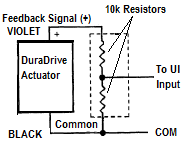
Use two 10k resistors as a voltage divider across the feedback leads with the center point connected to the controller input and the actuator common connected to the controller common.

Voltage Divider

NOTE: Not all actuators in this product family use the wire colors shown for the feedback output. Please refer to the actuator GI sheet for the correct colors.


 MNL / MNB Controller Analog Input Configuration

For actuators with a 0 VDC to 10 VDC feedback output:

Type= Volts
Linput = 0
Lscale = 0
Hinput = 5
Hscale = 100

This input configuration provides a 0 - 100% output corresponding to the Actuator Position, based on feedback voltage 0 VDC = 0% and 10 VDC = 100% of actuator travel. 

For actuators with a 2 VDC to 10 VDC feedback output:

Type= Volts
Linput = 1
Lscale = 0
Hinput = 5
Hscale = 100

This input configuration provides a 0 - 100% output corresponding to the Actuator Position, based on feedback voltage 2 VDC = 0% and 10 VDC = 100% of actuator travel.

Labels (1)
Labels:
  • TAC IA Series
Tags (1)
  • Find more articles tagged with:
  • 6313
Was this article helpful? Yes No
100% helpful (1/1)

Link copied. Please paste this link to share this article on your social media post.

To The Top!

Forums

  • APC UPS Data Center Backup Solutions
  • EcoStruxure IT
  • EcoStruxure Geo SCADA Expert
  • Metering & Power Quality
  • Schneider Electric Wiser

Knowledge Center

Events & webinars

Ideas

Blogs

Get Started

  • Ask the Community
  • Community Guidelines
  • Community User Guide
  • How-To & Best Practice
  • Experts Leaderboard
  • Contact Support
Brand-Logo
Subscribing is a smart move!
You can subscribe to this board after you log in or create your free account.
Forum-Icon

Create your free account or log in to subscribe to the board - and gain access to more than 10,000+ support articles along with insights from experts and peers.

Register today for FREE

Register Now

Already have an account? Login

Terms & Conditions Privacy Notice Change your Cookie Settings © 2025 Schneider Electric

This is a heading

With achievable small steps, users progress and continually feel satisfaction in task accomplishment.

Usetiful Onboarding Checklist remembers the progress of every user, allowing them to take bite-sized journeys and continue where they left.

of