Issue
In order to make the correct determination when selecting an actuator, it is important to first understand the difference between sourcing and sinking triacs. A triac will act as a switch. By triggering its gate electrode, it will either conduct alternating current or impede it. While it can be thought of as contacts on a relay, it is important to note that it is decidedly different.
Environment
- Xenta 121-FC, 121-HP
- Xenta 101-VF, 102-VF, 102-ES, 100-D (legacy)
Cause
A digital output on a Xenta 121 (labeled V1 through V4) utilizes a ground sourcing triode for alternating current (TRIAC). In general, a TRIAC will either be voltage sourcing or ground sourcing (also referred to as voltage sinking). The Xenta 121 using ground sourcing TRIACs will be a determining factor when selecting actuators to be driven by digital outputs.
Resolution
A TRIAC output is similar to a hardware switch in that it will either open or close a circuit, allowing or stopping the flow of current. Whether the internal side of the triac is connected to power or ground will determine whether it is a sourcing or sinking TRIAC.
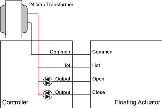
If the internal side of the TRIAC is connected to power, as shown in Figure 1, it will be considered a voltage sourcing TRIAC. When the output is activated, current will flow from the output, through the actuator, to ground. Most actuators are designed to accept voltage sourcing outputs from controllers.
Figure 1. Voltage Sourcing Triac Configuration
If the internal side of the TRIAC is connected to ground, as shown in Figure 2, it will be considered a ground sourcing (or voltage sinking) TRIAC. When the output is activated, current will flow from a power source, through the actuator, and into the output. Some actuators are designed to accept both voltage sourcing and voltage sinking outputs from controllers.
Figure 2. Voltage Sinking Triac Configuration
The digital outputs on terminals V1 through V4 of a Xenta 121 utilize ground sourcing triacs. The G terminal between each pair of triac outputs sources 24 Vac. It has direct continuity with the G power terminal. When the output is active, the triac will conduct current to ground completing the circuit.
Said another way, if the output is inactive, there will be a 24V potential between V1 and G0 (ground), but a 0V potential between V1 and G. When the output is active, there will be a 0V potential between V1 and G0, but a 24V potential between V1 and G. An actuator is wired between V1 and G, so the potential across these two terminals will dictate whether the actuator is on or off.
In one example, a 3-wire floating actuator is wired with OPEN, COM, CLOSE connected to V1, G, V2 respectively. There shouldn’t be a problem if the actuator is using the 24Vac signal to drive an AC motor. When the open command is active, the actuator will see a 24V potential across its contacts and drive the motor.
In another example, a 4-wire floating actuator is wired in the same manner, but now also requires its own 24Vac power signal to run some on-board logic. This example will not work because that actuator is expecting to see COM wired to ground, but it is in fact wired to the same 24Vac, resulting in 0V potential between power and ground of the actuator.
One solution is to use caution when selecting actuators to be driven by the Xenta 121. Avoid actuators designed to be controlled with voltage sourcing outputs. Another option is to use the triac outputs to close contacts on external relays that will source the necessary 24V as needed.
Another application of the digital outputs is to control the coil of a relay in order to open or close the circuit of another device, such as a low voltage terminal strip, fan motor contactor, etc. While some low voltage applications may function without the use of the relay between the 121 outputs and the device being controlled, this is generally not recommended and may negatively impact the reliability of the triac outputs.
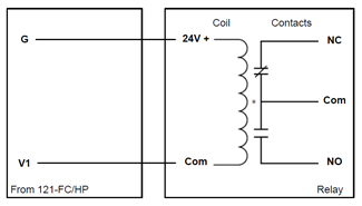
Because the triacs are ground sourcing and G provides 24V power to the circuit, they can be wired directly to the 2 legs of the relay coil, as shown in Figure 3 below. Using this configuration, the triac is isolated from any harmful current that may travel through the external relay contacts.
Figure 3. Wiring Configuration for Relay Control with Triac


